

Manifold for lube and seal oil apparatus
- Summary
- Abstract
- Description
- Claims
- Application Information
AI Technical Summary
Benefits of technology
Problems solved by technology
Method used
Image

Examples
Embodiment Construction
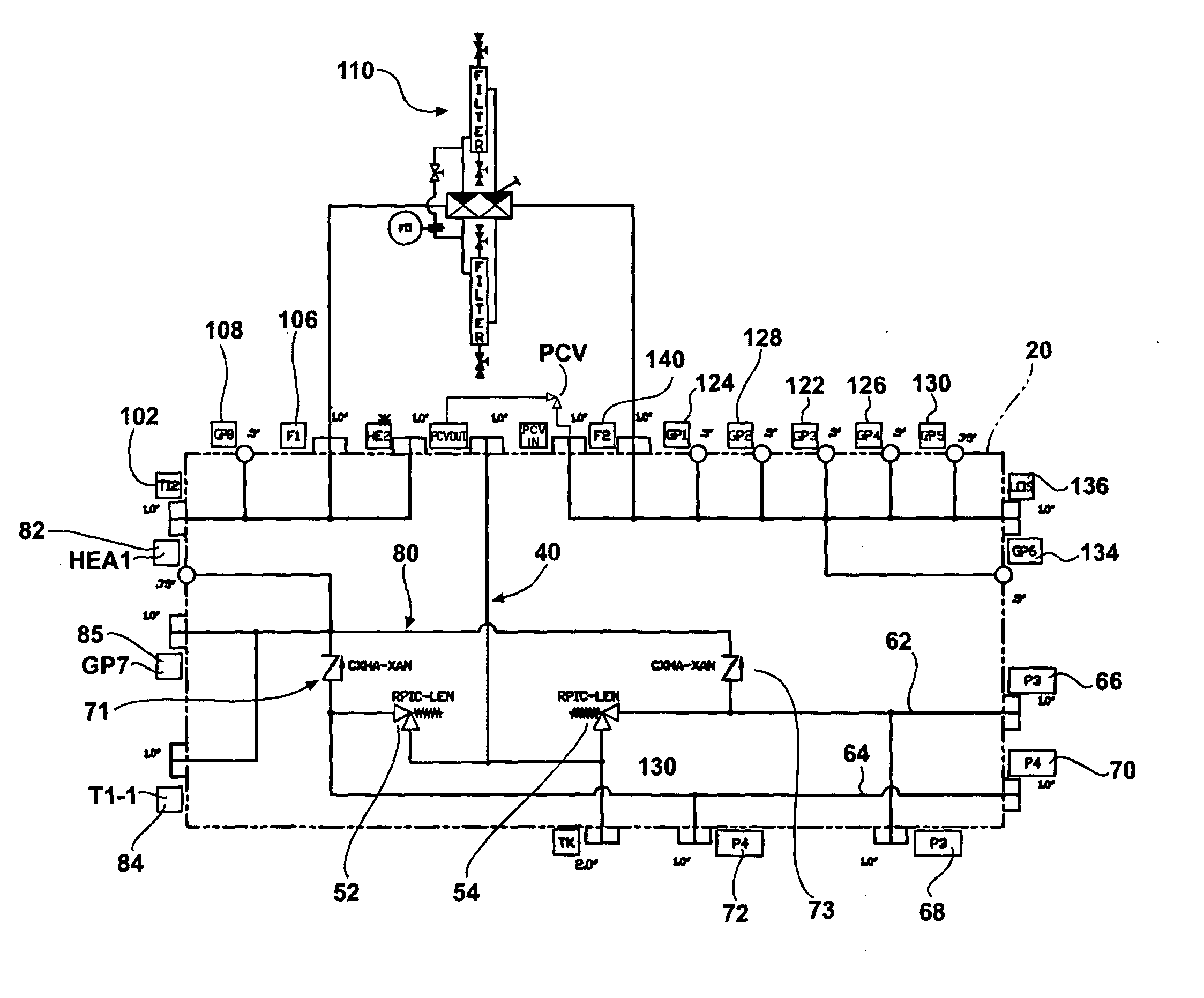
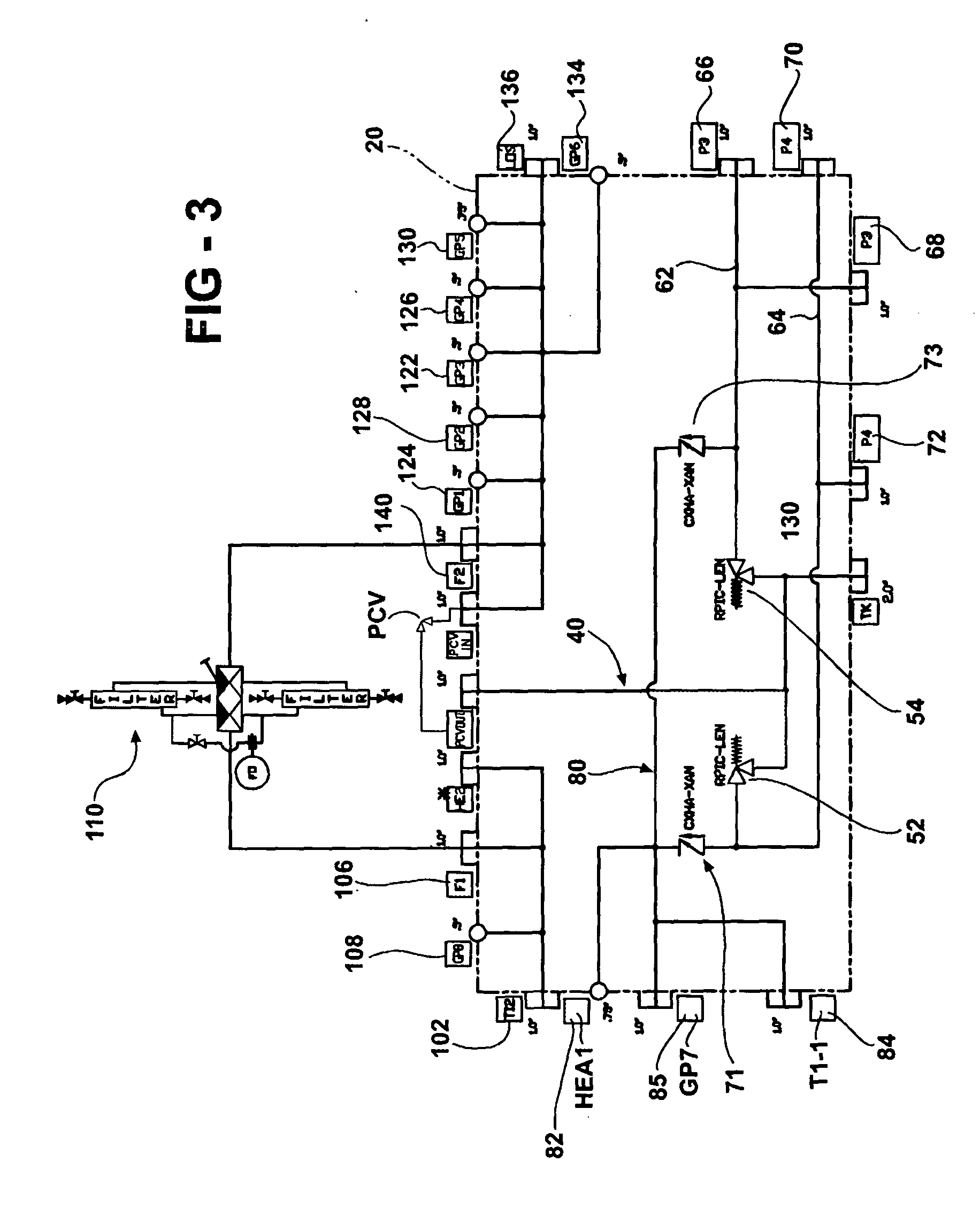
[0039] Referring now to the drawing, and to FIGS. 2-14 in particular, there is depicted a manifold 20 for use in connecting various components of a lube oil or seal oil supply system of a large process pump and drive apparatus.
[0040] The various components are attached to various ports on the manifold 20 and piped to other components in the pump and drive apparatus to complete the oil flow circuit of the pump and driver apparatus.
[0041] The manifold 20, according to the present invention, preferably is formed of a sold block of high strength material, such as a metal, preferably steel.
[0042] The block 20, which may have any shape, by example only has a generally polygonal shape in the form of a square or a rectangle formed by a front surface 22, a back or rear surface 24, opposed left and right side surfaces 26 and 28, a top surface 30 and a bottom surface 32.
[0043] A plurality of ports are formed on the various surfaces of the manifold 20 and internally coupled in fluid communi...
PUM
 Abstract
Description
Claims
Application Information