Parking mechanism

a technology of a parking mechanism and a rotor shaft, which is applied in the direction of brake systems, gearing, transportation and packaging, etc., can solve the problems of degrading the mountability of the transmission to the vehicle, unavoidable extension of the secondary pulley shaft in an axial direction, etc., and achieves the effect of effectively overcoming drawbacks and reducing the length of the secondary pulley sha

Inactive Publication Date: 2006-04-06
JATCO LTD
View PDF4 Cites 15 Cited by
  • Summary
  • Abstract
  • Description
  • Claims
  • Application Information

AI Technical Summary

Benefits of technology

[0004] In view of the above problems, it is an object of the present invention is to provide a parking mechanism which can effectively overcome drawbacks encountered in a conventional parking mechanism.
[0005] Another object of the present invention is to provide an improved parking mechanism by which the length of the secondary pulley shaft can be reduced even though the parking gear is disposed coaxial with the secondary pulley.

Problems solved by technology

However, in the above conventional technique, the parking gear is disposed to the side of the final reduction section of the secondary pulley shaft, and therefore the secondary pulley shaft unavoidably extends in an axial direction.
As a result, a transmission housing is also extended in the axial direction so that there arises a problem that mountability of the transmission to a vehicle is degraded.

Method used


Image

  • Parking mechanism
  • Parking mechanism
  • Parking mechanism

Examples


Embodiment Construction

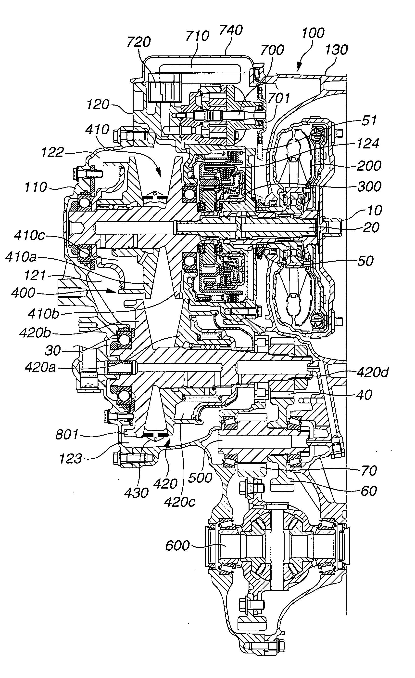
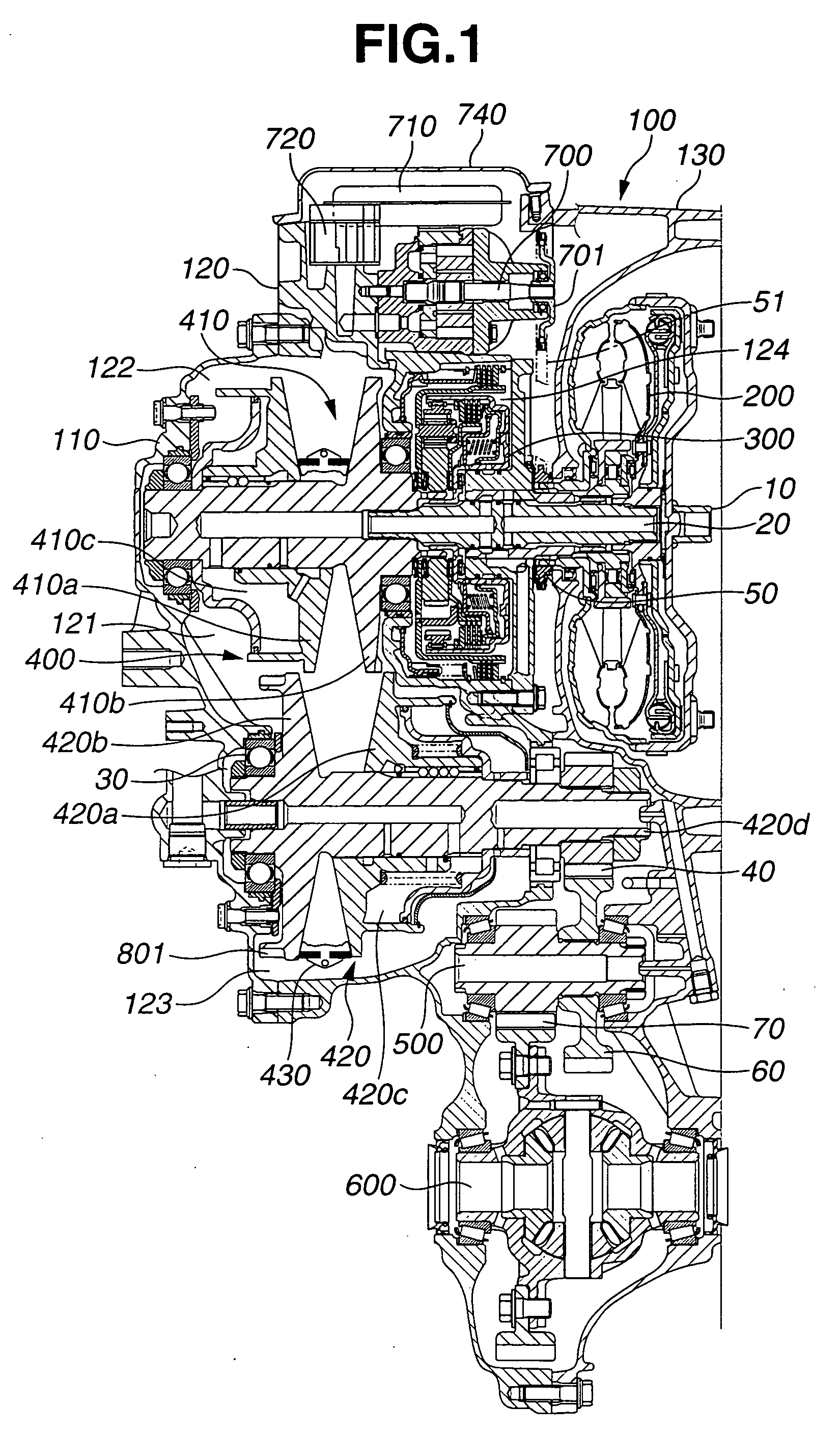
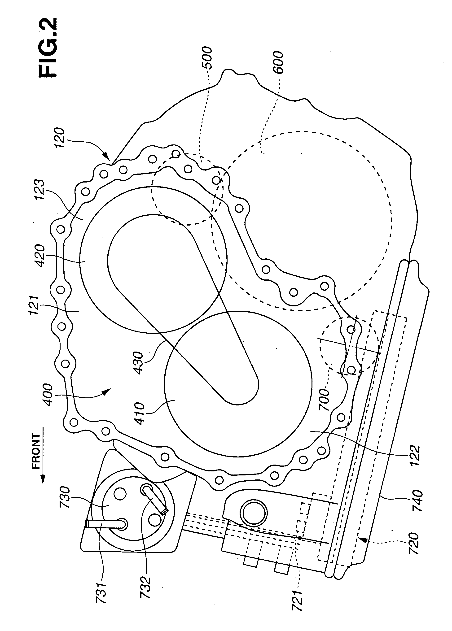
[0016] Referring now to FIGS. 1 to 6, an embodiment of a parking mechanism according to the present invention is illustrated. Hereinafter, discussion will be made on the embodiment of the parking mechanism with reference to figures, in which the figures are schematic illustrations for clearly presenting the idea of the present invention so as not to illustrate the accurate configuration of the parking mechanism.

[0017] Firstly, discussion will be made on the configuration of a transmission including the parking mechanism according to this embodiment.

[0018]FIG. 1 is a schematic cross-sectional view of a transmission including the parking mechanism of the embodiment according to the present invention. A transmission housing 100 includes a first housing 110, a second housing 120 and a third housing 130. The transmission housing 100 accommodates therein a torque converter 200 for amplifying torque from an engine. A forward-reverse changing mechanism 300 having a start-up clutch is conn...


PUM


Abstract

A parking mechanism includes a parking gear disposed within a belt type continuously variable transmission and coaxially fixed to a first rotational shaft of a secondary pulley. A parking pawl is rotatable on a plane perpendicular to the first rotational shaft and able to engage the parking gear with a transmission housing to stop rotation of the secondary pulley. A manual shaft is rotatable with an operational force of a driver for a lever. A detent mechanism is provided for changing a rotational movement of the manual shaft to a movement in a direction of the first rotational shaft. The movement in the direction of the first rotational shaft is transmitted to the parking pawl through a rod. A cam is disposed at an end section of the rod to change the movement in the first rotational shaft to a rotational movement on the plane perpendicular to the first rotational shaft. The parking gear is integrally formed at an outer peripheral section of a fixed sheave of the secondary pulley. The detent mechanism for operating the parking pawl is disposed to side of the movable sheave of the secondary pulley. At least a part of the rod is located above a belt passed on a primary pulley and the secondary pulley of the belt type continuously variable transmission.

Description

BACKGROUND OF THE INVENTION [0001] This invention relates to improvements in a parking mechanism by which a parking gear disposed coaxial with a secondary pulley of a belt type continuously variable transmission is engaged with a transmission housing through a parking pawl. [0002] Hitherto, various parking mechanisms of the above type have been proposed and put into practical use. One of such parking mechanisms is disclosed in a Japanese Patent Laid-open Publication No. 2004-44689. Briefly, in this parking mechanism, a parking gear is disposed to the side of a final reduction section of a secondary pulley shaft of a secondary pulley in a belt type continuously variable transmission. SUMMARY OF THE INVENTION [0003] However, in the above conventional technique, the parking gear is disposed to the side of the final reduction section of the secondary pulley shaft, and therefore the secondary pulley shaft unavoidably extends in an axial direction. As a result, a transmission housing is a...

Claims


Application Information

Patent Timeline
Patent Type & Authority Applications(United States)
IPC IPC(8): F16H57/00B60T1/06F16H9/12
CPCF16H9/00F16H63/3416F16H63/30
Inventor SUGANO, TAKUNAKATA, HITOSHI
Owner JATCO LTD
Why Eureka
Try Eureka