System and method for stabilizing a refrigerator storage bag to facilitate loading the bag with contents

a technology for storing bags and refrigerators, which is applied in the field of storage bags to facilitate the loading of the storage bags with contents, can solve the problems of troublesome process of transferring cleaned food items into the storage bags, complicated transfer of food items, bruises or other imperfections of fruits, etc., and achieves the effect of facilitating the pivoting of legs, and facilitating the movement of legs

Inactive Publication Date: 2006-04-06
HANDI HELPER
View PDF17 Cites 2 Cited by
  • Summary
  • Abstract
  • Description
  • Claims
  • Application Information

AI Technical Summary

Benefits of technology

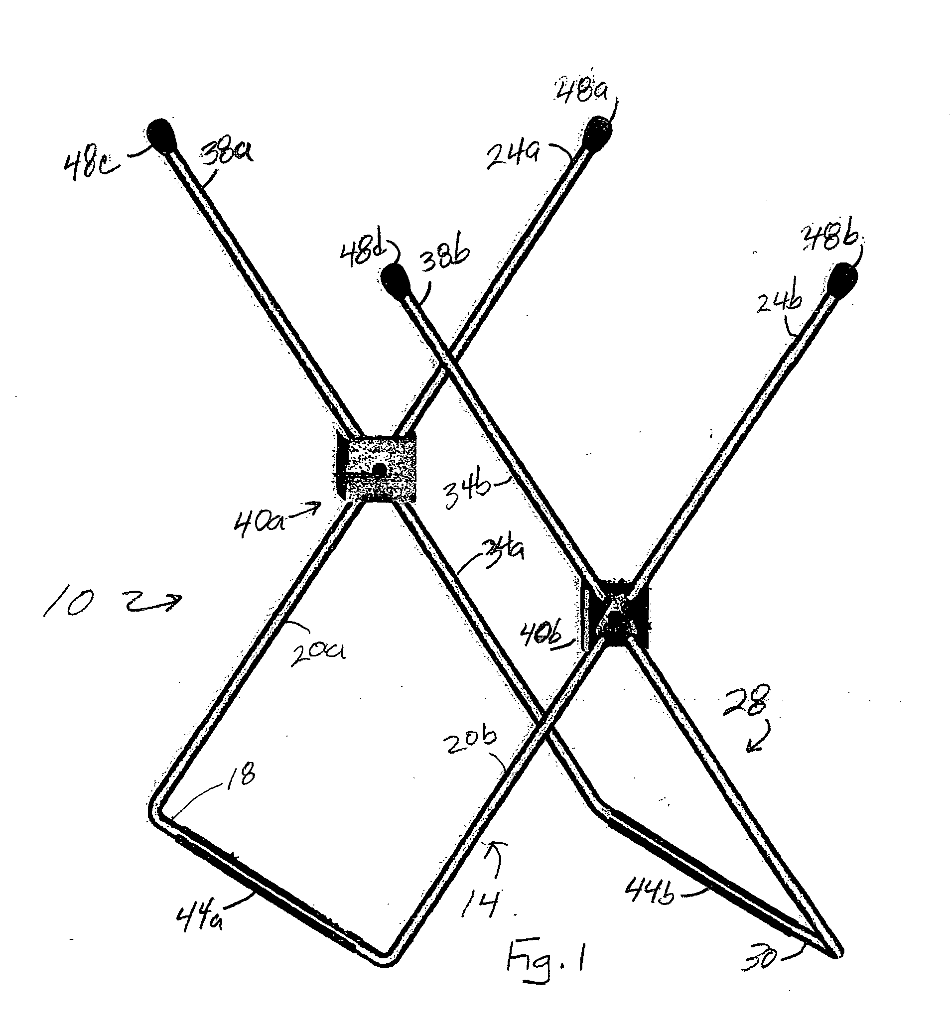
[0008] The U-shaped members of the system may have closed ends that are curved ends or the closed ends of the U-shaped members may be affixed to the legs extending from the closed ends at substantially a right angle. The latter configuration is preferred as it provides a more stable platform and more room for the expansion of the internal volume of the refrigerator bag. The closed ends may also have rubber tubing around them to provide a more slip resistant platform for the system.
[0009] The system of the present invention also includes a plurality of end caps. One end cap covers the distal end of each leg of the U-shaped members. The end caps are formed from a material having low coefficient of friction and are rounded to facilitate controlled slippage of the bag as its internal volume is filled. The end caps enable the refrigerator bag to be held during filling with reduced risk that the bag will catch on a distal end and tear as the weight of the contents within the bag exert a downward force on the mouth of the bag. Alternatively or additionally, the U-shaped members may be coated with a plastic or rubberized coating as known for covering dish drains or the like.
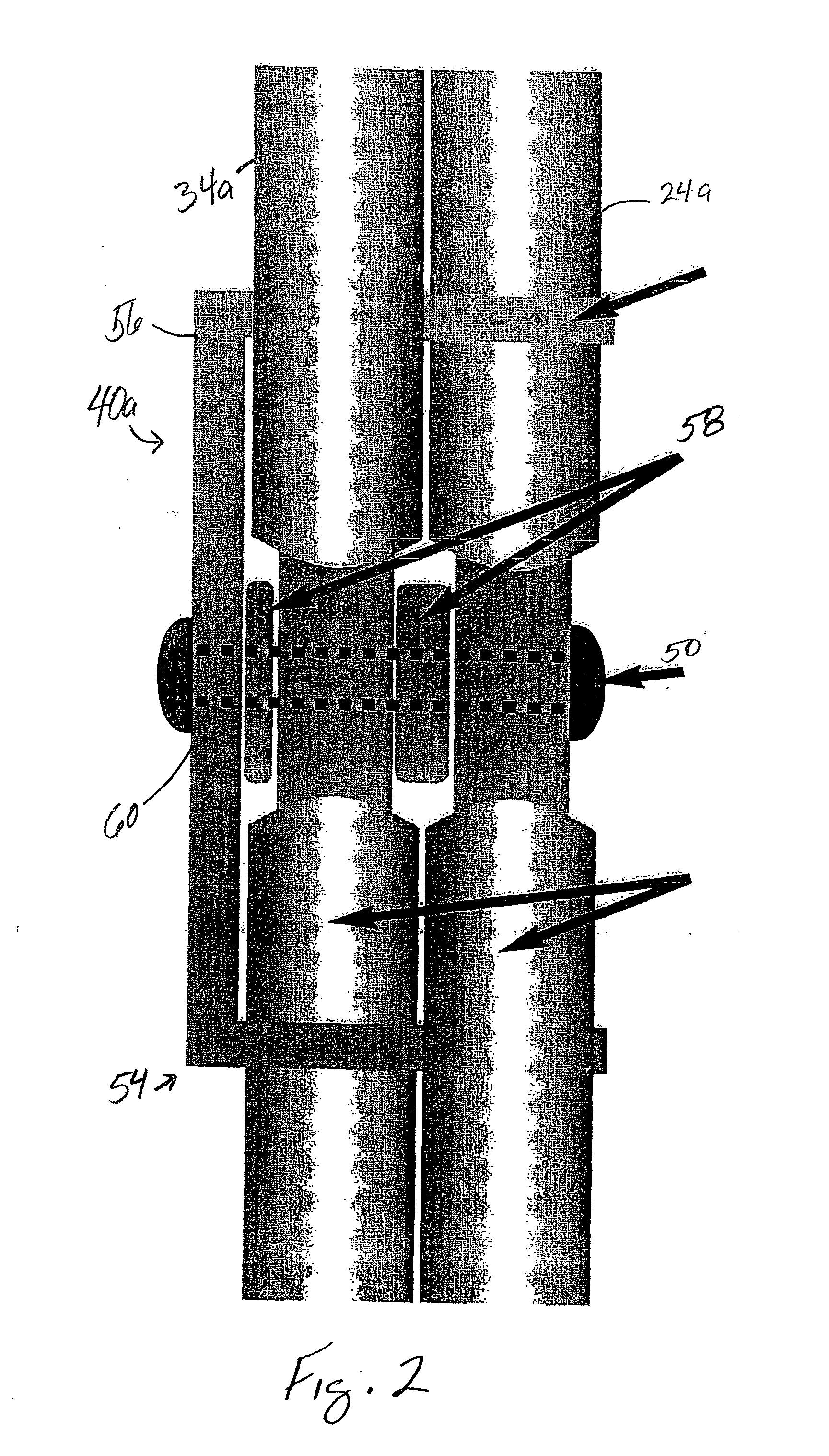
[0011] The pivot pin includes a portion that is threaded so the pin mates with a threaded hole in the bracket held in engagement with the legs joined together by the pin. The bracket may be mounted on the inside of the legs and the head of the pivot pin may be on the outside of the legs. The absence of threads in the holes of the legs through which the pivot pin passes facilitates the pivoting of the legs about the pivot pin. The U-shaped members may be formed from cylindrical material such 3 / 16ths diameter wire or tubular material. The cylindrical material from which the U-shaped members are formed is flattened about the holes through the legs of the U-shaped members to facilitate the movement of the legs past one another. Additionally, spacers are provided between the bracket and the legs as well as between the legs to further facilitate the movement of the legs relative to one another. The U-shaped members may also be flat bar material, although the stability of this type of frame may not be as stable as the cylindrical material.
[0012] The U-shaped members of the present invention are sized to correspond to the height of the refrigerator bags to be used with the system of the present invention. That is, the legs of the U-shaped members have a length that is approximately one inch less than the height of the bag to be used with the system. This differential enables the mouth of the refrigerator bag to be folded over the distal ends of the legs of the U-shaped members so the bottom of the bag rests on the level surface that supports the system of the present invention. For one gallon bags, the length of the legs of the U-shaped members is approximately 8½ inches, while the length of the legs of the U-shaped members for a system used with one quart bags is approximately 5¾ inches. Because the system of the present invention uses two frame members having open ends, the bag may be oriented so that its width at the bottom of the bag extends over the closed ends of the system. This enables the bag to more easily expand as its internal volume is filled and the weight of the contents also helps hold the system in place.
[0013] The system of the present invention may be used to stabilize a refrigerator storage bag during the placement of material within the bag. The method of using the system includes rotating two U-shaped members, each of which has a closed end and two legs extending from the closed end, that are joined to one another by a pair of couplers so that the closed ends of the U-shaped members move away from one another until stopped by the couplers. The closed ends of each U-shaped member are placed on a substantially level surface so that the ends of the legs extending from the closed ends of the U-shaped members remain stationary. A refrigerator bag mouth is folded over the ends of the legs of the closed ends of the U-shaped members so the bottom of the refrigerator bag rests on the closed ends of the U-shaped members. With the bag open and supported by the ends of the legs of the U-shaped members, material is poured into the refrigerator bag through the mouth of the bag. Once filled to a desired level, the refrigerator bag is closed by mating tongue and groove elements formed along an inside of the bag mouth so the bag and its contents can be stored. After use, the two U-shaped members are rotated so that the closed ends of the U-shaped members move towards one another so the bag frame formed by the two U-shaped members consumes less space during storage.
[0014] The system of the present invention may be made by coupling a first U-shaped member having a closed end and two legs extending from the closed end to a second U-shaped member having a closed end and two legs extending from the closed end so that the closed ends of the two U-shaped members pivot towards and away from one another. A stop is placed near a position where the first U-shaped member is coupled to the second U-shaped member to limit the outward travel of the closed ends when they pivot away from one another. The U-shaped members may be formed from tubular stock or cylindrical wire so that the closed ends of the first and the second U-shaped members are straight legs joined to the legs extending from each closed end at approximately a right angle. Each end of each leg extending from the closed end of the U-shaped members is covered with an end cap to complete the assembly.

Problems solved by technology

The process of transferring the cleaned food items into a refrigerator or freezer bag can be troublesome.
For example, berries are relatively fragile and rough treatment during transfer of the fruit to a bag may result in bruises or other imperfections for the fruit.
The transfer of food items may also be complicated by the shape and size of the food.
Attempts to “pour” strawberries from a container into bag can result in chaotic distribution of the berries, some of which actually land in the bag.
Others, however, bounce on the counter surface or even worse, fall to the floor.
Consequently, accidents in the transfer of food to bags for storage occur more frequently than desired.
The construction of the refrigerator / freezer storage bags also present problems with their easy use during transfer of food items to the bags.
Of course, this attempt to accurately place food items in this preferred target area of the bag mouth is usually hindered by difficulties in managing a container that is full of the food items that may or may not tumble or pour towards the intended target region.
Additionally, the flattening of the storage bags for storage in the box in which they were purchased also causes the mouth of the bag to resist remaining fully open.

Method used


Image

  • System and method for stabilizing a refrigerator storage bag to facilitate loading the bag with contents
  • System and method for stabilizing a refrigerator storage bag to facilitate loading the bag with contents
  • System and method for stabilizing a refrigerator storage bag to facilitate loading the bag with contents

Examples


Embodiment Construction

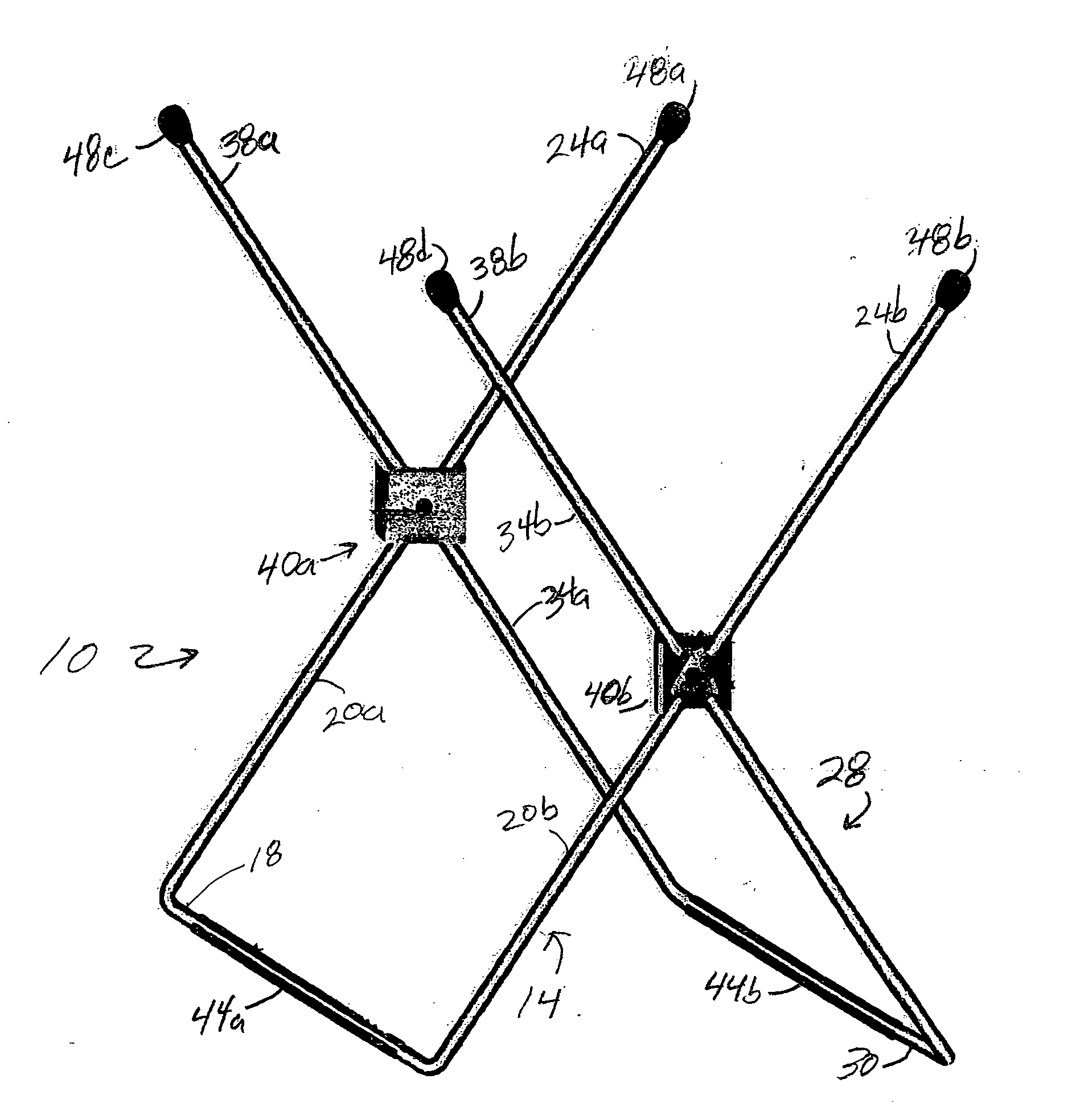
[0021]FIG. 1 shows a system 10 for stabilizing a refrigerator storage bag to facilitate the placement of material within the bag. The system 10 includes a first U-shaped frame member 14 having a closed end 18 and two legs 20a and 20b extending from the closed end 18 that terminate into distal ends 24a and 24b. The system 10 also includes a second U-shaped frame member 28 having a closed end 30 and two legs 34a and 34b extending from the closed end 30 that terminate into distal ends 38a and 38b. A first coupler 40a couples a first leg 20a of the first U-shaped member 14 to a first leg 34a of the second U-shaped member 28 and a second coupler 40b couples a second leg 20b of the first U-shaped member 14 to a second leg 34b of the second U-shaped member 28. The couplers limit the outward travel of the closed ends 18 and 30 of the U-shaped members 14 and 28 so that the first and the second distal ends of both U-shaped members remain stationary to hold in an open position a refrigerator b...


PUM


Abstract

A system assists kitchen workers with the filling of refrigerator bags by providing a system for stabilizing a refrigerator storage bag during the placement of material within the bag. The system includes a first U-shaped frame member having a closed end and two legs extending from the closed end that terminate into distal ends and a second U-shaped frame member having a closed end and two legs extending from the closed end that terminate into distal ends. A first coupler couples a first leg of the first U-shaped member to a first leg of the second U-shaped member and a second coupler couples a second leg of the first U-shaped member to a second leg of the second U-shaped member. The coupler limits the outward travel of the closed ends of the U-shaped members so that the first and the second distal ends of both U-shaped members remain stationary to hold in an open position a refrigerator bag having its mouth folded over the distal ends of the U-shaped members when the closed ends are rotated to the limit of their outward travel and the closed ends are placed on a level surface.

Description

FIELD OF THE INVENTION [0001] The present invention relates generally to bag holders, and more particularly, to bag holders that stabilize a bag to facilitate the placement of materials in the bag. BACKGROUND OF THE INVENTION [0002] Refrigerator bags are typically used to store leftovers from meals or to break large units of produce and other food items into quantities that are useable on a per meal basis. For example, fruit, such as various types of berries, may be purchased in large quantities and brought to a kitchen where they are cleaned for storage. The berries are then placed in refrigerator or freezer bags so they can be stored in a freezer to help preserve the freshness of the produce for later use. The bags used for storage may be selected to be a size that stores a quantity of berries that roughly corresponds with the amount of berries that may be used for a single meal or occasion. By segregating the berries into smaller units for storage, a single unit may be extracted ...

Claims


Application Information

Patent Timeline
Patent Type & Authority Applications(United States)
IPC IPC(8): A63B55/04
CPCB65B67/1205B65B67/1227
Inventor BADDOUR, PAUL M. JR.TOMLINSON, BRILEY H.
Owner HANDI HELPER
Why Eureka
Try Eureka