Method of measuring electric field distribution and electric field distribution measuring instrument

a technology of measuring instruments and electric fields, applied in the direction of instruments, resistance/reactance/impedence, material analysis, etc., can solve the problems of difficult to change spatial resolution, achieve high resolution of antennas, and reduce accuracy in measurement, so as to achieve easy change of resolution, increase resolution, and increase the effect of measurement speed

Inactive Publication Date: 2006-04-06
HITACHI LTD
View PDF8 Cites 24 Cited by
  • Summary
  • Abstract
  • Description
  • Claims
  • Application Information

AI Technical Summary

Benefits of technology

[0010] However, it has been unavoidable that the accuracy in measurement is lowered when, as in the conventional measurement, a miniaturized electric field antenna is used and it is brought close to a measurement object.
[0011] The reason therefor is that the electric field generated by the measurement object is greatly deviated by the electric field antenna that is brought close to the measurement object, as compared with the electric field when there is present no antenna and, consequently, a voltage due to induced charges on the antenna by the potential possessed by the measurement object is produced in the antenna, in excess of the desired induced voltage. This effect becomes more remarkable as the measurement frequency becomes “higher-frequency” to lower the measurement accuracy. A high-frequency range here means a frequency band being 1 GHz or higher.
[0014] The present invention has been made to address the above mentioned problem. Accordingly, an object of the present invention is to achieve measurement of two-dimensional or three-dimensional distribution of electric field intensity, phase, and direction in a high-frequency range with high accuracy.
[0018] Here, the interval of measurement of the surface potential distribution of the measurement object corresponds to the resolution in measurement of the electric field distribution, and therefore it is easy to change the resolution and increase the resolution higher.
[0019] Further, the potential distribution has no directivity, and therefore, once the potential distribution on the surface of the measurement object has been measured, electric field distribution in any direction on the surface of the measurement object and at positions near to or far from the measurement object can be calculated, and hence measurement speed also can be increased.

Problems solved by technology

However, it has been unavoidable that the accuracy in measurement is lowered when, as in the conventional measurement, a miniaturized electric field antenna is used and it is brought close to a measurement object.
Consequently, it becomes difficult to change spatial resolution and achieve high resolution of an antenna dependent on its size.

Method used


Image

  • Method of measuring electric field distribution and electric field distribution measuring instrument
  • Method of measuring electric field distribution and electric field distribution measuring instrument
  • Method of measuring electric field distribution and electric field distribution measuring instrument

Examples


Embodiment Construction

[0034] An embodiment of the present invention will be described with reference to the accompanying drawings.

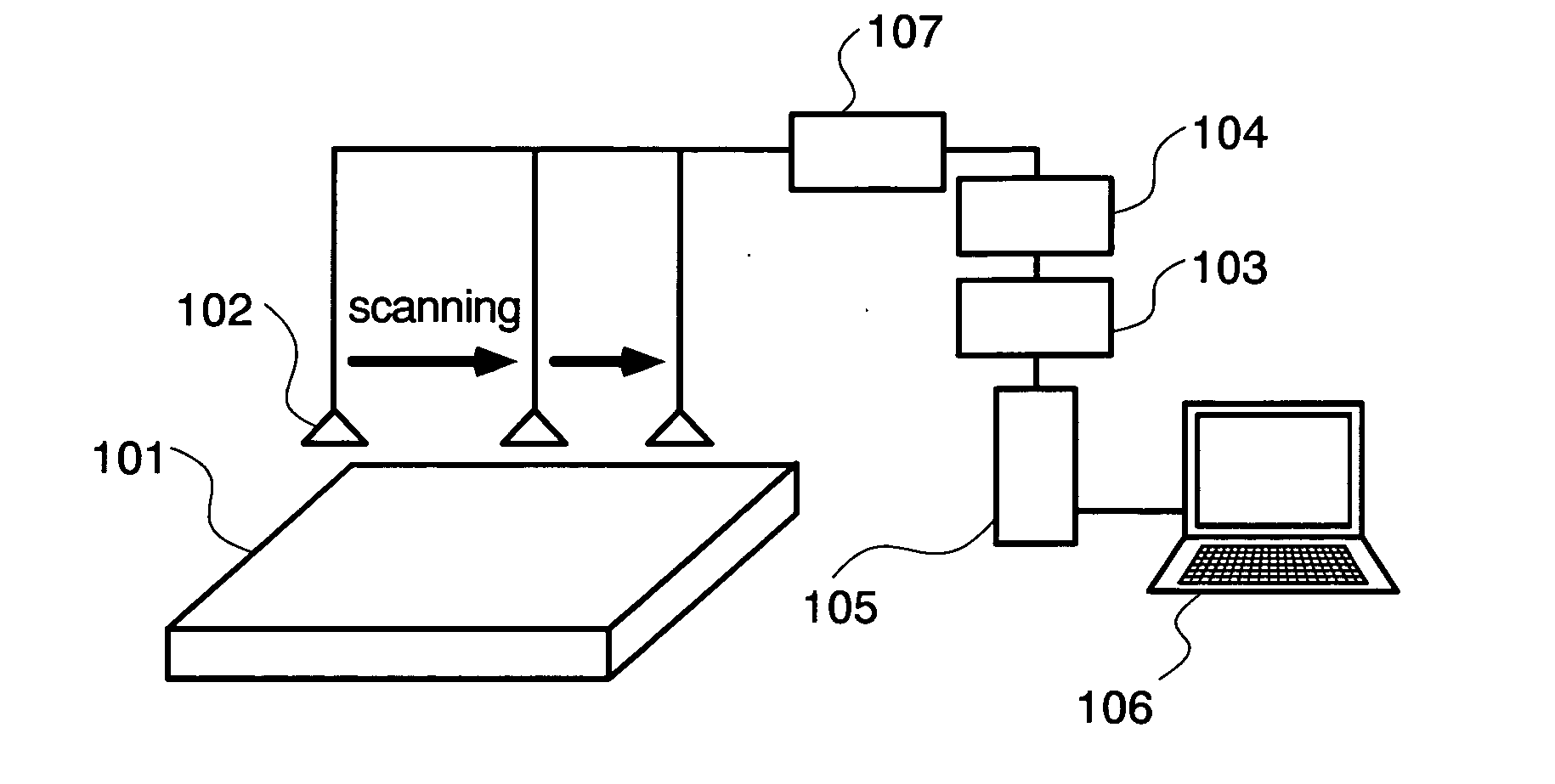
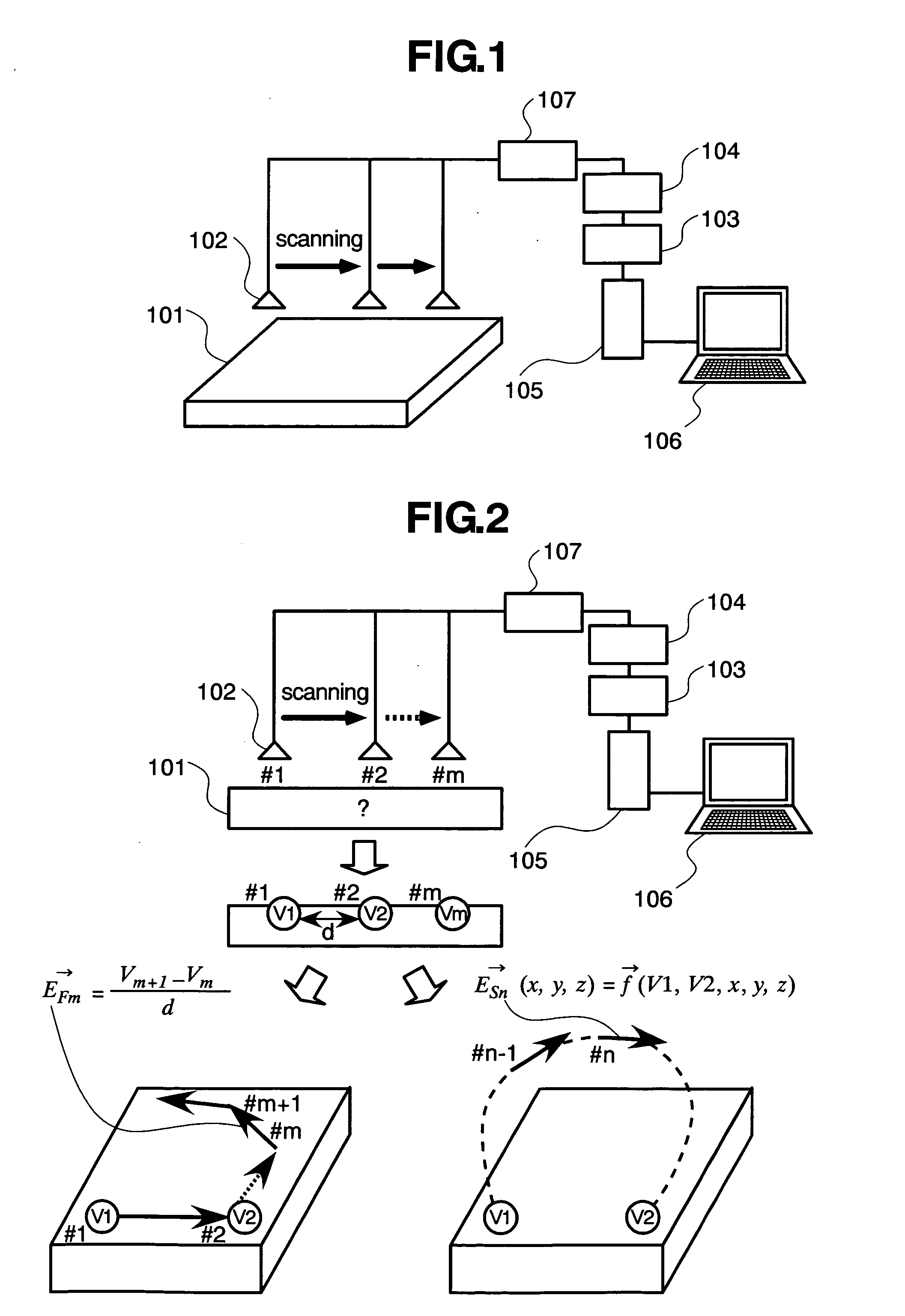
[0035]FIG. 1 shows a system block diagram of a measurement system.

[0036] The system as shown in FIG. 1 includes, as its constituent devices, a potential sensor 102 for measuring surface potential of a measurement object 101, a measuring device 103 for measuring a signal from the potential sensor, a filter or an amplifier 104 for changing the signal from the potential sensor into a signal with a desired magnitude or a frequency component, a CPU (a central-processing-unit) for calculating the intensity, phase, and direction of electric fields or Poynting vectors on the surface of the measurement object or an arbitrary point in a space from the results of the surface potential measurement, a computer 105 including a memory and a storage device storing therein programs for use in the above calculations, and the like, a display device 106 for displaying results of measurement, an...


PUM


Abstract

A method and apparatus for measuring an electric field distribution according to the present invention calculates a distribution of electric field intensity and its direction at arbitrary positions on the surface of the electronic apparatus or its circumference with use of data of measurement positions and measurement results of a potential distribution on a surface of an electronic apparatus. Further, it clearly indicates a flow of electromagnetic energy on the surface or in the circumference of the electronic apparatus by applying mathematical treatments to a magnetic field distribution at circumferential positions of the electronic apparatus. Thus, a distribution of high-frequency electric field generated from the electronic apparatus is measured with high accuracy.

Description

[0001] The present application claims priority from Japanese application JP2004-283028 filed on Sep. 29, 2004, the content of which is hereby incorporated by reference into this application. BACKGROUND OF THE INVENTION [0002] 1. Field of the Invention [0003] The present invention relates to a technology for measuring intensity, phase, and direction distributions of electric fields occurring inside or outside a measurement object. [0004] 2. Description of the Related Art [0005] In order to identify positions and propagation paths of electromagnetic energy in an electronic apparatus causing malfunctions and the like due to electromagnetic mutual interference, it is required to measure intensity, phase, and direction of electric fields or magnetic fields generated from the electronic apparatus in a two dimensional or three dimensional manner. [0006] Heretofore, the present inventors have invented a magnetic field measuring antenna or a measuring method and apparatus as disclosed in Jap...

Claims


Application Information

Patent Timeline
Patent Type & Authority Applications(United States)
IPC IPC(8): G01R27/04
CPCG01R29/0814G01R29/0871G01R29/0892G01R31/002
Inventor FUNATO, HIROKISUGA, TAKASHIUESAKA, KOUICHINAKAMURA, SATOSHI
Owner HITACHI LTD
Why Eureka
Try Eureka