Oscillator starting control circuit

a control circuit and oscillator technology, applied in the direction of oscillator starters, electrical equipment, generators, etc., can solve the problems of easy variation of starting time, limited voltage to be applied to varicap diodes, and inability to carry out an application to oscillating circuits using mos variable capacity having a high sensitivity, etc., to achieve accurate setting of stabilized starting period, stabilize starting time, and shorten starting time

Inactive Publication Date: 2006-04-06
COLLABO INNOVATIONS INC
View PDF4 Cites 6 Cited by
  • Summary
  • Abstract
  • Description
  • Claims
  • Application Information

AI Technical Summary

Benefits of technology

[0033] According to the structure, it is possible to accurately set a stabilized starting period.
[0034] According to the oscillator starting control circuit in accordance with the invention, a starting time can be shortened remarkably, and furthermore, the starting time can be stabilized. Moreover, it is possible to stabilize an oscillating frequency after starting an oscillating circuit.
[0035] By using the oscillator starting control circuit according to the invention in portable equipment represented by a cell phone, furthermore, it is possible to shorten a starting time during an intermittent operation, thereby prolonging a time required for an OFF state. Consequently, it is possible to enhance the effect of reducing a consumed power.

Problems solved by technology

With this structure, a voltage to be applied to the varicap diode is limited.
Moreover, it is impossible to carry out an application to an oscillating circuit using an MOS variable capacity having a high sensitivity.
Furthermore, there is a drawback that the starting time is easily varied depending on the starting conditions of a power to be applied to the oscillating circuit.
After starting the oscillating circuit, therefore, it is impossible to output a certain oscillating frequency.

Method used


Image

  • Oscillator starting control circuit
  • Oscillator starting control circuit
  • Oscillator starting control circuit

Examples


first embodiment

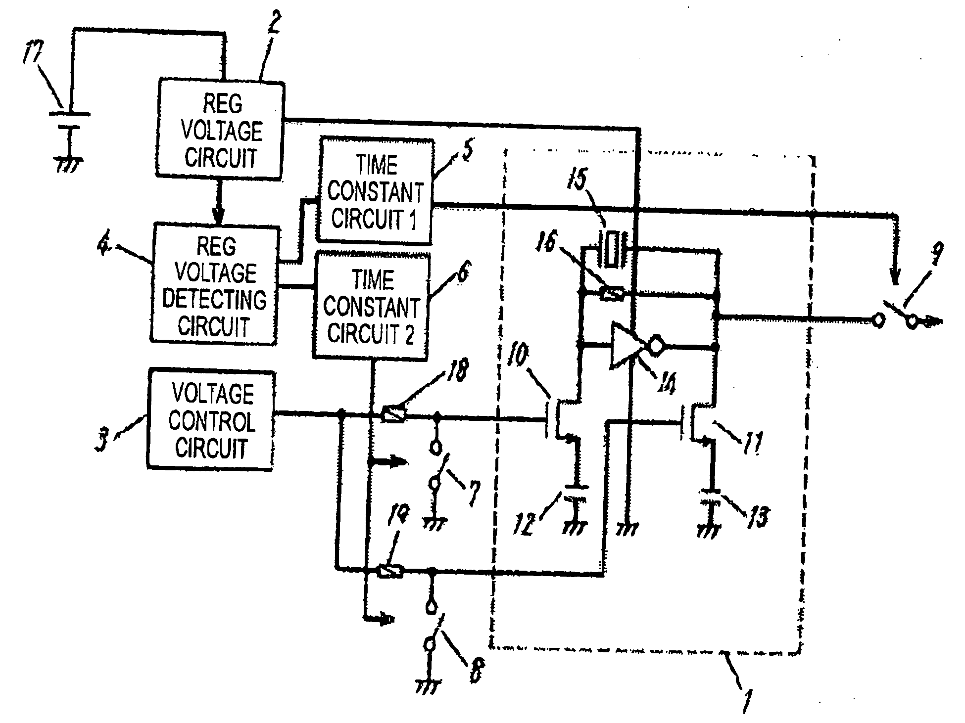
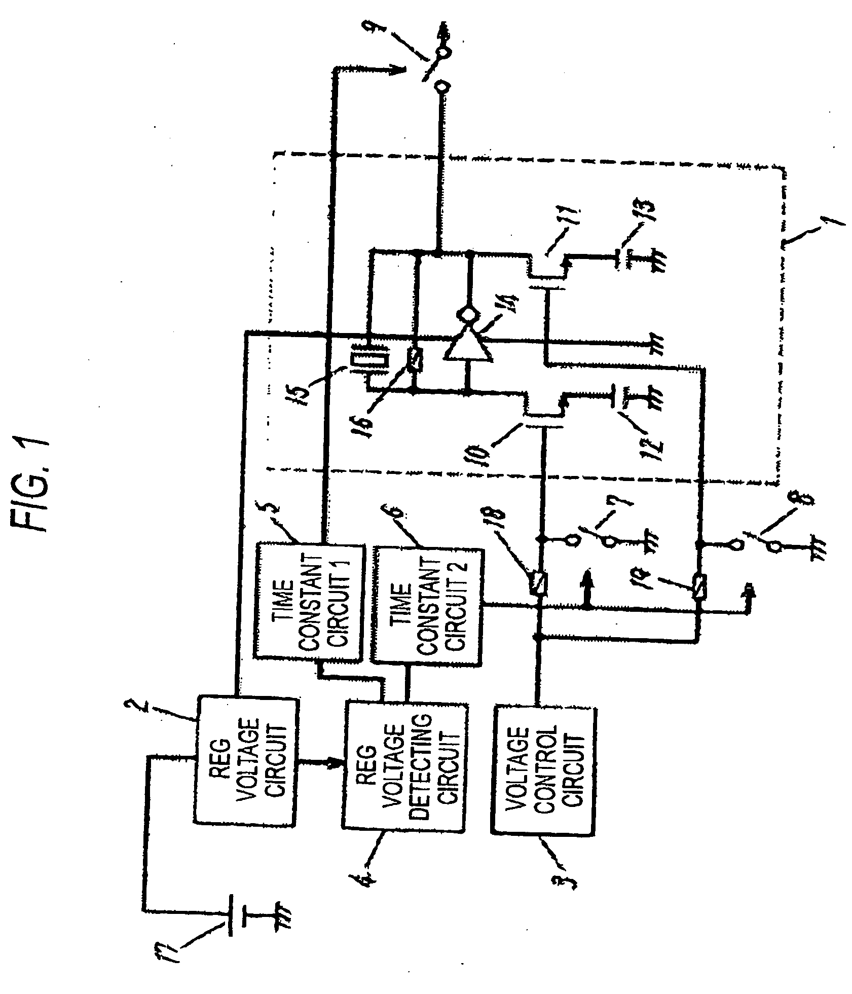
[0052]FIG. 1 is a diagram showing a first embodiment of an oscillator starting control circuit according to the invention.

[0053] In FIG. 1, an REG voltage is applied to an oscillating circuit (1: oscillator) by an REG voltage circuit (2) to which a source voltage (17) is applied. The oscillating circuit (1) in FIG. 1 is a crystal oscillating circuit in which an input and an output of an inverter (14) is connected to both ends of a crystal oscillator (15) and both ends of a resistor (16), and the input is connected to a drain of an MOS variable capacity (10) and the output is connected to a drain of an MOS variable capacity (11), the MOS variable capacity (10) has a source connected to a fixed capacity (12) and the MOS variable capacity (11) has a source connected to a fixed capacity (13), and the other ends of the fixed capacities (12, 13) are connected to a GND.

[0054] Furthermore, a resistor (18) and a switch (7: a first switch) are connected to a gate of the NOS variable capacit...

second embodiment

[0072]FIG. 9 is a diagram showing a second embodiment of an oscillator starting control circuit in which the shape of the variable capacitance unit (10) and a method of applying a voltage from the voltage control circuits (3, 22) are different from those of the first embodiment.

[0073] In FIG. 9, an REG voltage is applied to an oscillating circuit (1) by an REG voltage circuit (2) to which a source voltage (17) is applied The oscillating circuit (1) in FIG. 9 is a crystal oscillating circuit in which an input and an output in an inverter (14) are connected to both ends of a crystal oscillator (15) and both ends of a resistor (16), and furthermore, the input and the output are connected to capacities (20) and (21) for cutting a control voltage to be applied to the MOS variable capacity (10), and the MOS variable capacity (10) has a gate connected to the first control voltage circuit (3) and a drain connected to the second control voltage circuit (22) and the MOS variable capacity (10...

third embodiment

[0078]FIG. 10 is a diagram showing a third embodiment in which a floating node is fixed to an oscillation stabilizing voltage by a switch (24) for fixing the floating node of a variable capacitance unit (10) for a constant time generated by a time constant circuit 1 (6) and the floating node is then returned into a normal floating state after the constant time.

[0079] An oscillating circuit (1) shown in FIG. 10 is a crystal oscillating circuit in which a resistor (23) and the switch (24 a third switch) are connected to a source of the MOS variable capacity (10) of the oscillating circuit (1) in FIG. 9 and a third control voltage circuit (25) is connected to the other end of the resistor (23).

[0080] On the other hand, an REG voltage detecting circuit (4) is connected in such a manner that a signal for detecting a rise in an REG voltage circuit (2) is transmitted thereto and is connected to transmit the same signal to time constant circuits 1 and 2 (6, 5) Furthermore, the time consta...


PUM


Abstract

It is an object to provide an oscillator starting control circuit capable of shortening a starting time and stably controlling the starting time, and furthermore, stabilizing an oscillating frequency after starting an oscillating circuit. [Means for Resolution] An oscillating circuit (1) is a crystal oscillating circuit in which an input and an output of an inverter (14) are connected to both ends of a crystal oscillator (15) and both ends of a resistor (16), the input is connected to a drain of an MOS variable capacity (10), the output is connected to a drain of an MOS variable capacity (11), a source of the MOS variable capacity (10) is connected to a fixed capacity (12), a source of the MOS variable capacity (11) is connected to a fixed capacity (13), and the other ends of the fixed capacities (12, 13) are connected to a GND. Furthermore, a resistor (18) and a switch (7) are connected to a gate of the MOS variable capacity (10), a resistor (19) and a switch (8) are connected to a gate of the MOS variable capacity (11), and the other ends of the resistors (18, 19) are connected to each other, and furthermore, to a voltage control circuit (3).

Description

BACKGROUND OF THE INVENTION [0001] 1. Field of the Invention [0002] The present invention relates to an oscillator starting control circuit which is suitable for shortening and controlling a starting time of a crystal oscillator circuit and stabilizing an oscillating frequency. [0003] 2. Description of the Related Art [0004] In recent years, a crystal oscillating circuit has often been used as a frequency to be a reference in electronic equipment, and furthermore, a transmission data rate has also been increased. In such electronic equipment, an intermittent operation is carried out in order to reduce a consumed power. For this reason, there has been desired an oscillating circuit for carrying out starting in a short time for the crystal oscillating circuit used as a frequency to be their reference and outputting a constant oscillating frequency by a low consumed power Therefore, the crystal oscillating circuit is very useful for a circuit technique. [0005] Moreover, a frequency out...

Claims


Application Information

Patent Timeline
Patent Type & Authority Applications(United States)
IPC IPC(8): H03B5/32
CPCH03B5/06H03B5/36H03L3/00
Inventor NAGATOMO, KEISHINGU, KEIGOTAKEUCHI, HISATO
Owner COLLABO INNOVATIONS INC
Why Eureka
Try Eureka