Supercharge Your Innovation With Domain-Expert AI Agents!

Automatic gain control system and method

a gain control system and automatic technology, applied in transmission systems, analogue/digital conversion, instruments, etc., can solve the problems of reducing the time required to bring the input to the analogue-to-digital converter out of saturation, and affecting the accuracy of the received signal

Active Publication Date: 2006-04-06
WIPRO LTD
View PDF6 Cites 14 Cited by
  • Summary
  • Abstract
  • Description
  • Claims
  • Application Information

AI Technical Summary

Benefits of technology

[0007] In general terms, the invention provides an automatic gain control system and method in which the output from a digital-to-analogue converter is used to generate the control signals to a number of variable gain control components. By monitoring the amplitude of the signal from the variable gain control components and performing an adjustment, the time required to place the amplitude of any signal within a much smaller window which is close to a reference level is reduced. Subsequently, fine gain adjustment may be performed. As a result, the time required to bring the input to the analogue-to-digital converter out of saturation is significantly reduced.
[0022] The systems and methods described herein are intended primarily for the application to burst first mode communication systems. However, they may also be easily implemented in a fully digital circuitry.

Problems solved by technology

Moreover, the correct operation of analogue-to-digital converters can only be achieved if the excursion of the input signal is within the converter-specific dynamic range, thus avoiding saturation.
In systems where the signal is applied to an analogue-to-digital converter, if the level of the signal being applied to the analogue-to-digital converter exceeds the dynamic range of the analogue-to-digital converter, the control loop will have difficulty in reaching a steady state.
This problem is particularly evident in applications where the received signal consists of packets of data with a short header code (preamble) during which time the automatic gain control circuitry needs to settle.
Traditional automatic gain control circuits in most modern receivers have difficulty achieving precise gain adjustment of the received signal to a desired level within such a short response time.

Method used


Image

  • Automatic gain control system and method
  • Automatic gain control system and method
  • Automatic gain control system and method

Examples


case 1

Case 1

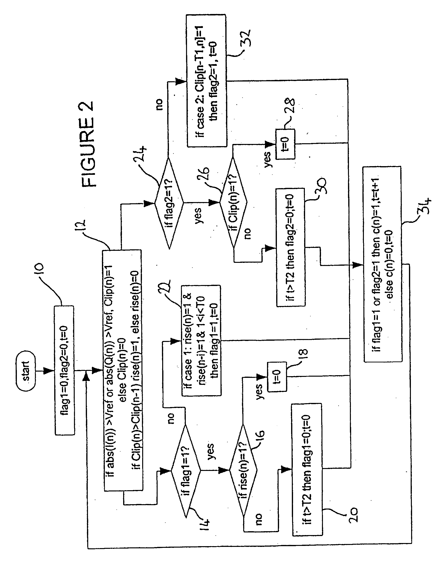
[0045] This rule is applied to the incoming signal as follows. The incoming signal is sampled at intervals ti for a period T0, during which time every sample of the incoming signal V (that is abs(I) and abs(Q)) is compared with Vref. If rise(n) is again recorded as being 1 during the period T0, flag 1 is set to 1 (that is to TRUE) for a period T2. If rise(n)=1 is not detected during the period T2, then flag 1 is reset to 0 after time T2.

[0046] However, if during the period T2, rise(n) is detected as being 1, then flag 1 is maintained at flag 1=1 for a further period T2 from this instant.

[0047] Similarly, if a further instance of rise(n)=1 occurs during the period T2, flag 1 will be extended by an additional period T2 from this instant, on each occasion.

case 2

Case 2

[0048] This rule is also applied to the incoming signal in the second stage 12. Initially, the incoming signal V is compared with Vref at intervals ti for a period T1. If every sample of V is greater than or equal to Vref during the period T1, that is Clip(n)=1, flag 2 is set to 1 for a period T2.

[0049] If, within the period T2, the sampled incoming signal V is greater than Vref, that is Clip(n)=1, then the sampling period is extended by a further period T2 from that instant and the signal is continuously sampled in this extended period.

[0050] If, within the period T2, a sample of the incoming signal V is not greater than Vref, that is Clip(n)=0, then flag 2 is reset to 0 at a time T2 from this instant.

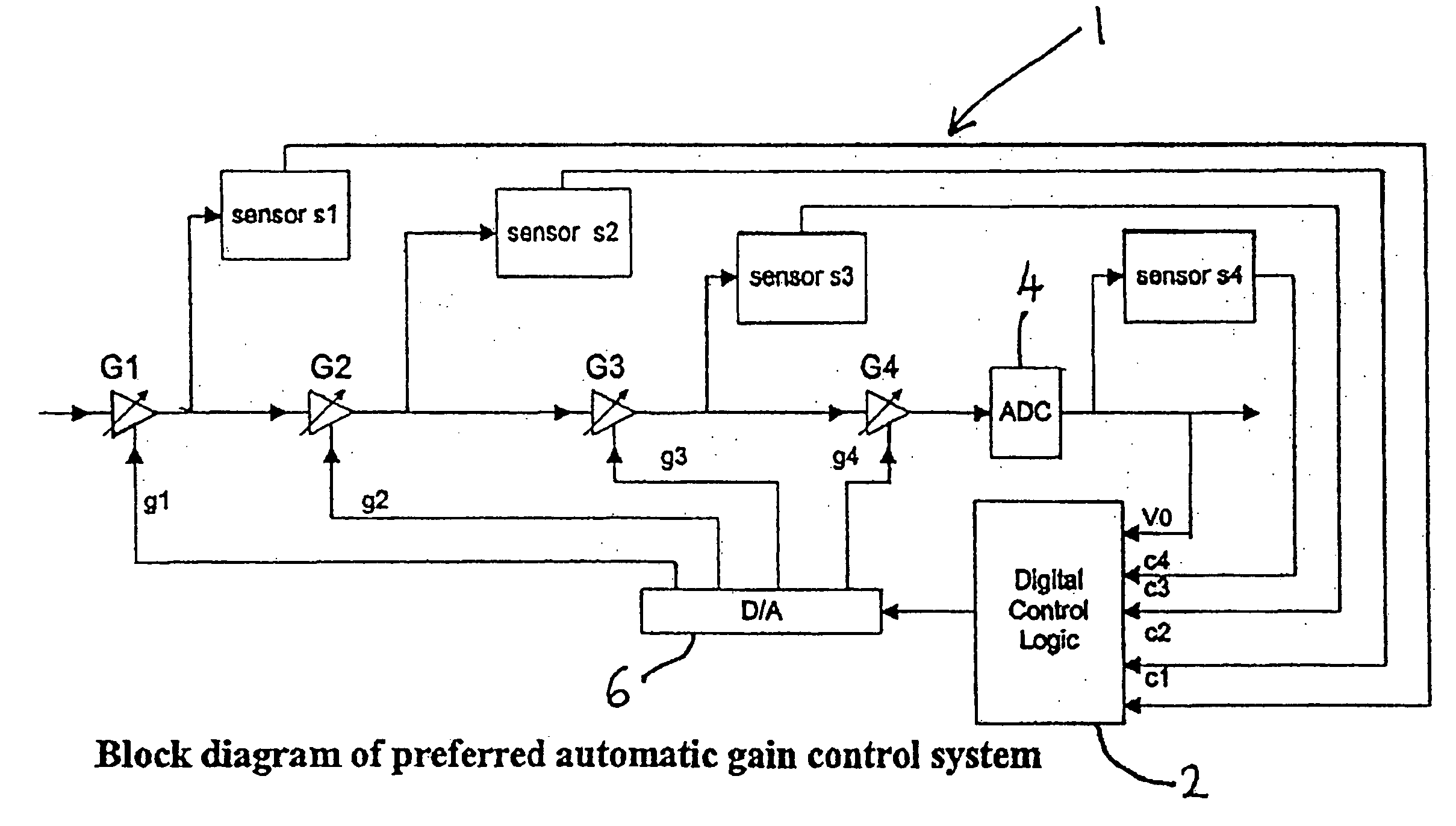
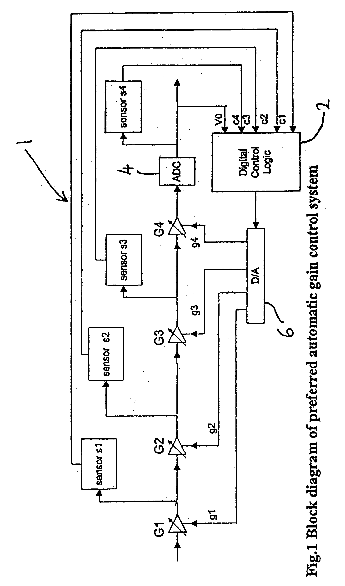
[0051] As shown in FIG. 2, the two cases 1 and 2 are treated independently but preferably simultaneously.

[0052] For both cases, the samples are counted in the time counter (not shown) and the periods T0 to T2 are determined by the time counter.

[0053] For each sample of the ...


PUM


Abstract

An automatic gain control system,comprises a number of variable gain stages connected in series and a number of sensors, the input of each sensor being connected to a respective output of the variable gain stages. The input of an analogue-to-digital converter is connected to the output of one of the variable gain stages. The input of a control unit is connected to the outputs of the sensors and to the output of the analogue-to-digital converter. The input of a digital-to-analogue converter is connected to the output of the control unit, and the control inputs of each of the variable gain stages is connected to an output of the digital-to-analogue converter. The outputs of the digital-to-analogue converter are used to control the gains of the variable gain stages. Also disclosed is a method for automatically controlling gain in a receiver system.

Description

FIELD OF THE INVENTION [0001] The present invention relates to an automatic gain control system and a method for automatically controlling gain, for example in a receiver system. BACKGROUND OF THE INVENTION [0002] Automatic gain control (AGC) is an essential element in modern communication receivers enabling the estimation of signal strength and the automatic adjustment of the amplification gain in order to maintain a relatively constant signal level. In typical conventional systems, such as in burst-mode wireless communication systems, for example, the Bluetooth system, the received signal needs to be level-adjusted prior to further processing. Furthermore, it is desirable to have a signal with a relatively constant strength (amplitude) to enable the full range of the processing circuits to be used. Moreover, the correct operation of analogue-to-digital converters can only be achieved if the excursion of the input signal is within the converter-specific dynamic range, thus avoiding...

Claims


Application Information

Patent Timeline
Patent Type & Authority Applications(United States)
IPC IPC(8): H03M1/12
CPCH03M1/185
Inventor YANG, CHUNHUAYEO, THENG TEETOMISAWA, MASAYUKI
Owner WIPRO LTD
Features
  • R&D
  • Intellectual Property
  • Life Sciences
  • Materials
  • Tech Scout
  • Unparalleled Data Quality
  • Higher Quality Content
  • 60% Fewer Hallucinations
Learn More