Antenna and dielectric substrate for antenna

a dielectric substrate and antenna technology, applied in the direction of resonant antennas, antenna earthings, elongated active element feeds, etc., can solve the problems of difficult control of antenna characteristics, bad vswr characteristics, difficult to control antenna characteristics, etc., to achieve the effect of reducing the volume of the antenna, enhancing the miniaturization, and controlling the antenna characteristi

Inactive Publication Date: 2006-04-06
TAIYO YUDEN KK
View PDF42 Cites 2 Cited by
  • Summary
  • Abstract
  • Description
  • Claims
  • Application Information

AI Technical Summary

Benefits of technology

[0016] By providing the cut-out portion, the miniaturization can be further enhanced, and a current path for obtaining radiation in the low frequency range can be secured. With respect to the conventional technique in which the radiation conductor is vertically erected to the ground surface, the antenna characteristic cannot be controlled by the cut-out portion by the cut-out portion. However, according to this invention, the antenna characteristic can be controlled. Furthermore, since the ground pattern and the planar element are juxtaposed with each other, the mount volume of the antenna can be reduced, the antenna characteristic, particularly the impedance characteristic, can be easily controlled, and the wide bandwidth can be achieved.
[0017] Incidentally, the aforementioned planar element may be disposed so that the edge portion other than the cut-out portion of the planar element is opposite to the ground pattern. If the ground pattern portion and the planar element portion can be separated from each other, the miniaturization of the antenna can be facilitated. Furthermore, other parts may be mounted on the ground pattern. In this case, the miniaturization can be enhanced also as the entire communication device.

Problems solved by technology

The antenna resonates at a frequency lower than fL because of the element 1014a, however, the VSWR characteristic is bad.
As described above, though various antennas have been hitherto known, the conventional vertical mount type monopole antennas have problems that their sizes are large, and it is difficult to control the antenna characteristic since it is difficult to control the distance between the radiation conductor and the ground surface.
Furthermore, the conventional symmetrical type dipole antennas also have a problem that it is difficult to control the antenna characteristic since the radiation conductors have the same shape, thereby it is difficult to control the distance between the radiation conductors.
In addition, though it is described that the glass antenna device for the automobile telephone disclosed in JP-A-8-213820 has an excellent sensitivity and directional characteristic at 800 MHz and 1.5 GHz, the bandwidth is not sufficiently broad.
Furthermore, this publication never discloses provision of any cut-out portion.
In addition, though the antenna of US-A-2002-122010A1 aims at miniaturization, the structure that the driven element is provided within the ground element cannot achieve the sufficient miniaturization because the ground element fully surrounds the driven element.

Method used


Image

  • Antenna and dielectric substrate for antenna
  • Antenna and dielectric substrate for antenna
  • Antenna and dielectric substrate for antenna

Examples


first embodiment

[0053] Preferred embodiments according to the present invention will be described with reference to the accompanying drawings. [0054] 1. First Embodiment

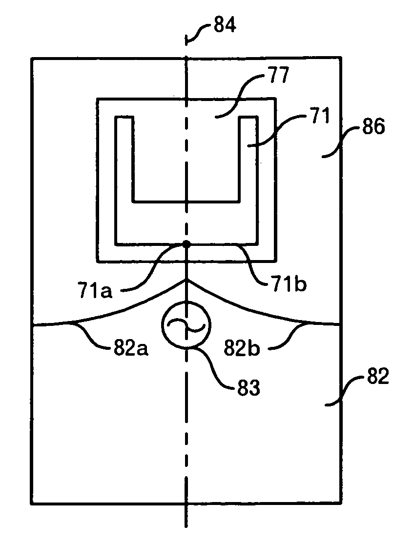
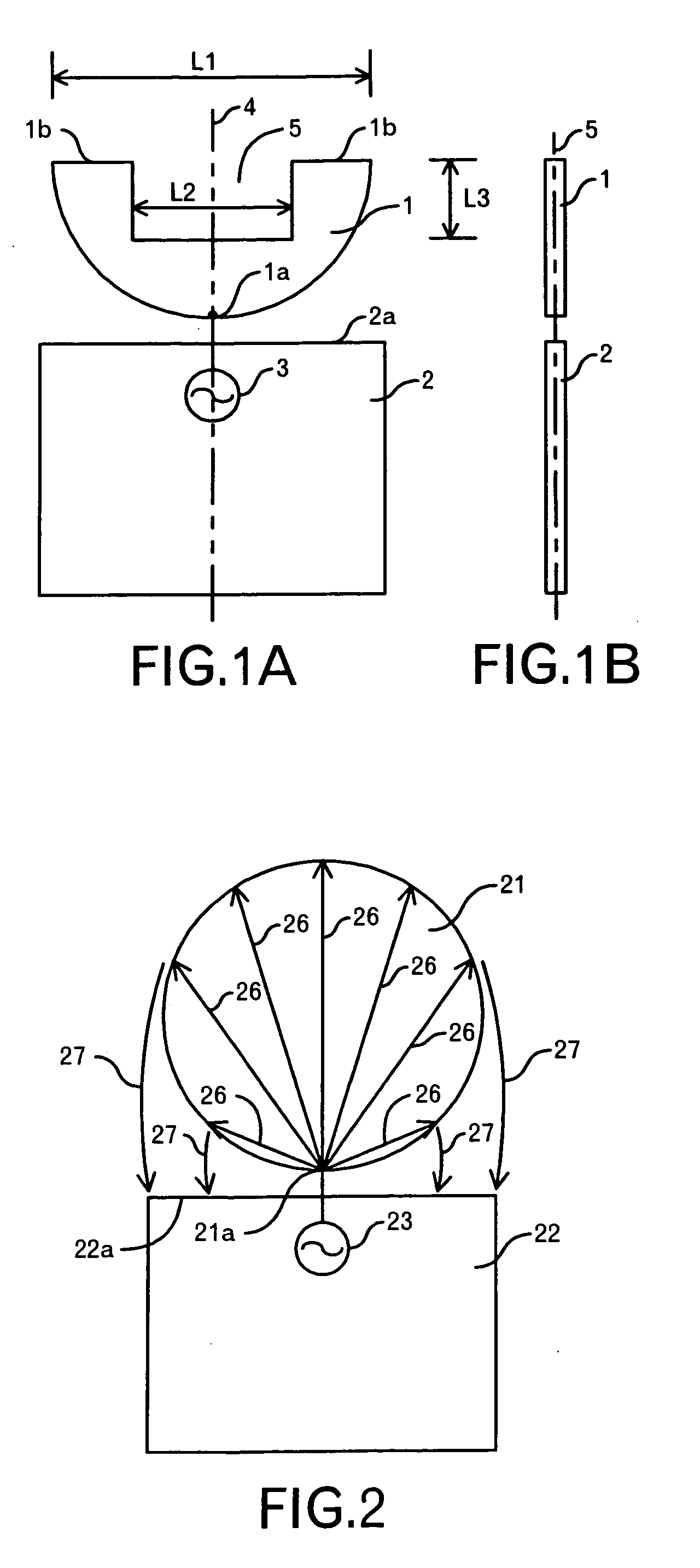
[0055] The structure of an antenna according to a first embodiment of the present invention is shown in FIG. 1A and FIG. 1B. The antenna according to this embodiment is composed of a planar element 1 formed of a semicircular conductive flat plate and having a cut-out portion 5, a ground pattern 2 juxtaposed with the planar element 1, and a high-frequency power source 3 connected to the feed point 1a of the planar element 1. The diameter L1 of the planar element 1 is set to 20 mm, for example. The aperture L2 of the cut-out portion 5 is set to 10 mm, for example, and the rectangular concavity whose depth is L3 (=5 mm) is formed from the top portion 1b (i.e. the edge portion farthest from the feed point 1a) of the planar element 1 toward the ground pattern 2 side, for example. The feed point 1a is located at such a position that the ...

second embodiment

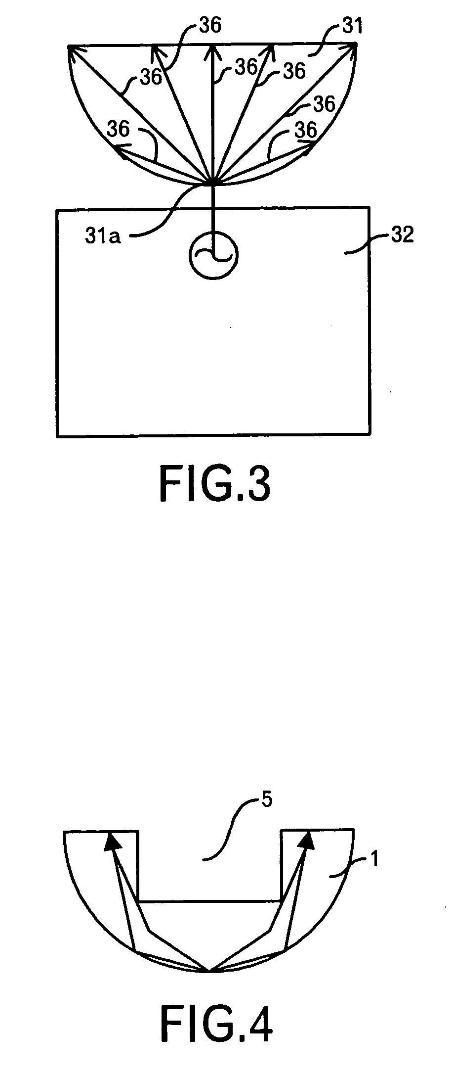
[0070] Furthermore, the shape of the cut-out portion 5 is not limited to the rectangular shape. For example, an inverted triangular cut-out portion 5 may be used. In this case, the feed point 1a and one apex of the inverted triangle are arranged to be located on the line 4. Still furthermore, the cut-out portion 5 may be designed in a trapezoidal shape. In the case of the trapezoid, if the bottom side is designed to be longer than the top side, the detour length at which the current path detours around the cut-out portion 5 is increased. Accordingly, the current path in the planar element 1 can be more increased. The corners of the cut-out portion 5 may be rounded. [0071] 2. Second Embodiment

[0072]FIG. 6 shows the structure of an antenna according to a second embodiment of the present invention. In this embodiment, an example will be explained in which a planar element 41 which is formed of a semicircular conductive flat plate and is equipped with a cut-out portion 45, and a ground...

third embodiment

[0076]FIG. 7 is a graph showing the impedance characteristic of the antenna according to this embodiment. In FIG. 7, the axis of ordinate represents VSWR and the axis of abscissa represents the frequency (GHz) Since the frequency bandwidth in which VSRW is not more than 2.5 extends from about 2.9 GHz to about 9.5 GHz, this embodiment has achieved a wide bandwidth antenna. The value of VSWR approaches 2 at about 6 GHz, however, this is permissible. The frequency at which VSWR becomes 2.5 is an extremely low frequency (i.e. about 2.9 GHz) because the cut-out portion 45 is provided. [0077] 3. Third Embodiment

[0078]FIG. 8 shows the structure of an antenna according to a third embodiment of the present invention. In this embodiment, an example will be explained in which a planar element 51 which is formed of a rectangular conductive flat plate and equipped with a cut-out portion 55, and a ground pattern 52 are formed on a printed circuit board (FR-4, Teflon (registered trademark) or the...


PUM


Abstract

An antenna comprises a ground pattern, and a planar element that is fed and equipped with a cut-out portion provided from the farthest edge portion formed from the feed position toward the ground pattern side, and the ground pattern and the planar element are juxtaposed with each other. The cut-out portion enables to further miniaturize the antenna and secure current paths to obtain radiation in a low-frequency range. Since the ground pattern and the planar element are juxtaposed with each other, the mount volume of the antenna can be reduced, and the antenna characteristic, particularly the impedance characteristic, can be easily controlled, and the bandwidth can be widened.

Description

[0001] This is a Divisional of application Ser. No. 10 / 654,432 filed Sep. 4, 2003. The entire disclosure of the prior application is hereby incorporated by reference herein in its entirety.TECHNICAL FIELD OF THE INVENTION [0002] The present invention relates to a wide bandwidth antenna. BACKGROUND OF THE INVENTION [0003] For example, JP-A-57-142003 discloses the following antennas. That is, it discloses a monopole antenna in which a flat-plate type radiation element 1001 having a disc shape is erected vertically to an earth plate or the ground 1002 as shown in FIGS. 22A-1 and 22A-2. This monopole antenna is designed so that a high-frequency power source 1004 and the radiation element 1001 are connected to each other through a power feeder 1003 and the height of the top portion of the radiation element 1001 is set to a quarter wavelength. Furthermore, it also discloses a monopole antenna in which a flat-plate type radiation element 1005 whose upper peripheral edge portion has a shape...

Claims


Application Information

Patent Timeline
Patent Type & Authority Applications(United States)
IPC IPC(8): H01Q1/38H01Q1/48H01Q1/36H01Q5/00H01Q9/28H01Q9/38H01Q9/40
CPCH01Q1/38H01Q9/40
Inventor OKADO, HIRONORI
Owner TAIYO YUDEN KK
Why Eureka
Try Eureka