Multi-antenna handheld wireless communication device

Inactive Publication Date: 2006-04-06
GOOGLE TECH HLDG LLC
View PDF2 Cites 37 Cited by
  • Summary
  • Abstract
  • Description
  • Claims
  • Application Information

AI Technical Summary

Problems solved by technology

However, any such plans must work within the bandwidth constraints imposed by government regulations.
In endeavoring to apply MIMO methods to handheld devices one faces limitations imposed by constraints on the practical external design of handheld devices (having multiple antennas protruding in different directions is undesirable), the limited size of handheld devices, and in particular the limited size of the ground structures (e.g., Printed Circuit Board (PCB) ground plane

Method used


Image

  • Multi-antenna handheld wireless communication device
  • Multi-antenna handheld wireless communication device
  • Multi-antenna handheld wireless communication device

Examples


first embodiment

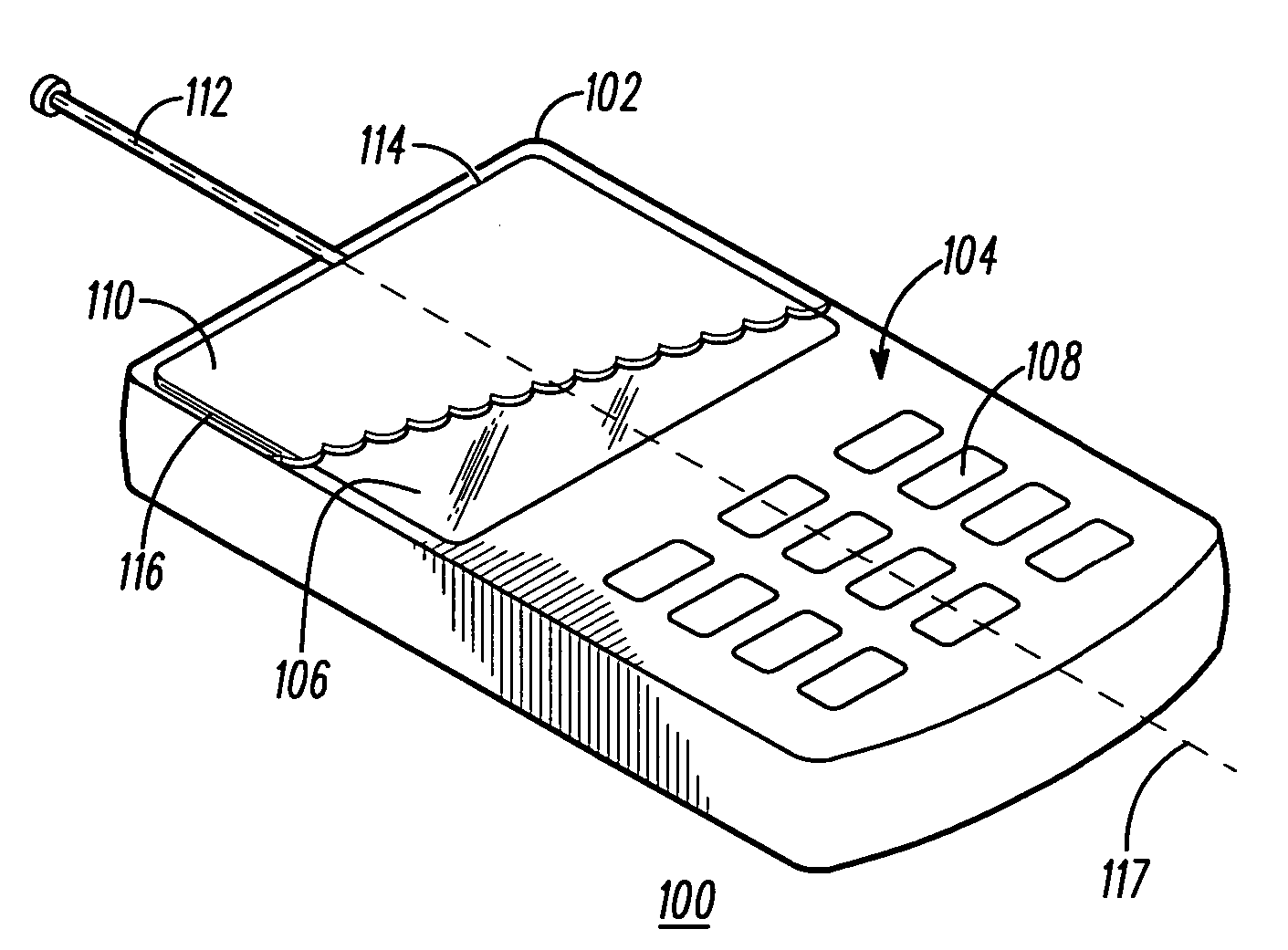
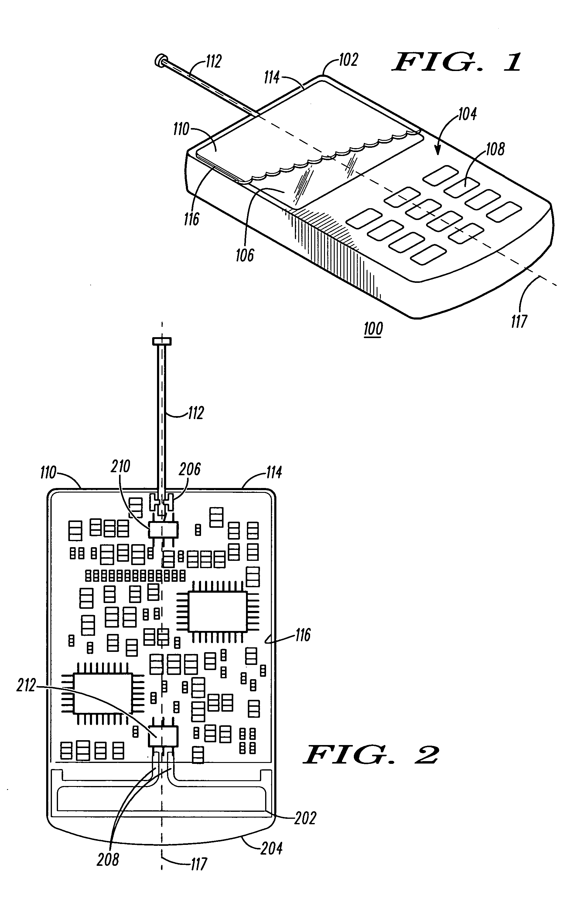
[0029]FIG. 1 is a perspective view of a handheld wireless communication device 100 according to a The device 100 comprises a housing 102 that includes a front surface 104. A display 106 and a keypad 108 are located at the front surface 104 of the housing 102. A populated circuit substrate, in particular a first printed circuit board 110 is located in the housing 102. The first circuit board 110 includes a ground plane 116. A first antenna, which is a monopole antenna 112 extends from the first circuit board 110 out of the housing 102. The monopole antenna 112 is a single ended antenna which is to say that it is driven by applying a signal to a single terminal 206 (FIG. 2). The monopole antenna 112 is an unbalanced feed antenna which is to say that the monopole antenna 112 is driven by applying a signal between the monopole antenna 112 and the ground plane 116. The monopole antenna 112 is mounted near a top end 114 of the first circuit board 110 at a transverse center of the first c...

fifth embodiment

[0042] Antennas included in a third, a fourth, and a fifth embodiment described below are alternatively used as the first antenna 634 and the second antenna 640.

second embodiment

[0043]FIG. 7 is a partial block diagram of the handheld wireless communication device 100 shown in FIG. 1 according to a FIG. 7 shows an alternative transceiver 700 architecture for the device 100. The alternative transceiver 700 comprises a multiple output decoder 702 and a multiple input encoder 704 coupled to I / O 624. The multiple output decoder 702 and the multiple input encoder 704 use MIMO processing to enhance the spectral efficiency of communications conducted with the device 100. Although the internal details of MIMO processing are outside the focus of the present description, it is important to note in the present context that MIMO processing calls for the use of multiple antennas capable of transmitting and receiving decorrelated signals such as provided in a practical compact form in the device 100 as described above with reference to FIGS. 1-5. Note that the word “output” in “multiple output decoder”702 refers to outputs of a wireless channel, and the term “input” in “...


PUM


Abstract

Antenna systems for handheld wireless communication devices (100) that comprise a first unbalanced feed antenna (112, 718, 802, 1204, 1812) and a second balanced feed antenna dipole antenna (202, 716, 804, 1202, 1802) that are located next to a ground structure (116, 810, 1210, 1824) for the handheld wireless communication devices are provided. The balanced feed dipole antenna and the unbalanced feed antenna exhibit disparate spatial-polarization patterns which are suitable for use with a MIMO transceiver, and the decorrelation of signals received by the two antennas is preserved due to a low level of coupling through the ground structure, which is due, in part, to differences in the symmetry properties of current patterns in the ground structure that are associated with the operation of the two antennas. The two antennas can also be used in a transceiver (629) that uses separate antennas to receive and transmit.

Description

FIELD OF THE INVENTION [0001] The present invention relates in handheld wireless communication devices. BACKGROUND OF THE INVENTION [0002] The adaptation of wireless communication devices over the past decade has brought about a sea change in the area of personal communications. Handheld wireless communication devices allow instant and nearly ubiquitous access to telephone networks and the internet. [0003] Looking to the future, there is an interest in enabling handheld wireless communication devices to handle higher bandwidth communication. Among other things, this would facilitate sending and receiving of video, music, and performing other high speed file transfer via handheld wireless communication devices. However, any such plans must work within the bandwidth constraints imposed by government regulations. In order to maximize the effective data bandwidth of a given frequency band, researchers have developed a new class of physical layer communication techniques known as Multi-I...

Claims


Application Information

Patent Timeline
IPC IPC(8): H01Q1/24H01Q9/16H01Q1/48
CPCH01Q1/242H01Q1/243H01Q1/362H01Q1/48H01Q9/16H01Q9/30H01Q21/28H01Q21/30H01Q9/38H01Q9/0407
Inventor RICHARD, MIGUEL A.FARAONE, ANTONIO
Owner GOOGLE TECH HLDG LLC
Why Eureka
Try Eureka