Liquid crystal display

a liquid crystal display and display device technology, applied in static indicating devices, instruments, non-linear optics, etc., can solve the problems of low contrast ratio, difficult recognition of transmissive emission light, and increase in power consumption of el elements, so as to improve visibility, improve display quality, and reduce power consumption

Inactive Publication Date: 2006-04-06
CITIZEN WATCH CO LTD
View PDF5 Cites 182 Cited by
  • Summary
  • Abstract
  • Description
  • Claims
  • Application Information

AI Technical Summary

Benefits of technology

[0015] Further, a switching element is provided in the liquid crystal display device and a liquid crystal display pixel electrode and the light emitting element are controlled by the switching element, so that it is made possible to improve display quality on a liquid crystal display panel, achieve low power consumption and improve visibility.

Problems solved by technology

However, in the display devices that use the conventional EL elements, when light intensity of an external light source is very strong, since intensity of transmissive emission light from the EL element is less than the intensity of reflective light at the cathode electrode, the transmissive emission light can be hardly recognized, and the contrast ratio is low.
To avoid such an inconvenience, it is necessary to increase the intensity of the light emitted from the EL element; however, this results in increase in the power consumption of the EL element.
If the power consumption increases, battery drain becomes sharp in the small-sized portable information devices, the portable telephones, the personal digital assistants (PDAs), the small-sized game machines, the watches, or the like, so that a sufficient use time can not be secured.
On the other hand, in the reflective liquid crystal display devices, even if the light intensity of the external light source is strong, such an inconvenience in the EL element described above does not occur.
Instead, in an environment that light intensity of an external light source is weak or an environment that light from an external light source is not present, display becomes unrecognizable.
In the transflective-type liquid crystal display devices or the reflective liquid crystal display devices having a front illumination constituted of a light guiding plate arranged on the viewer's side of a liquid crystal display panel, since it is necessary to provide light source outside the liquid crystal display panel, thinning or weight-reduction is limited.
Connection of a light source or a constitution where the light source and the liquid crystal display element are formed in a module is complicated.
Further, in the liquid crystal display devices that incorporate the conventional EL elements therein, such a constitution is not employed that desired displaying is conducted by controlling light emitting intensity of the EL element, but the light emitting element is merely used as an illumination light source for the liquid crystal display element.
Therefore, even during lightening of the EL element, it is necessary to drive the liquid crystal display element, which results in increase in power consumption.

Method used


Image

  • Liquid crystal display
  • Liquid crystal display
  • Liquid crystal display

Examples


first embodiment

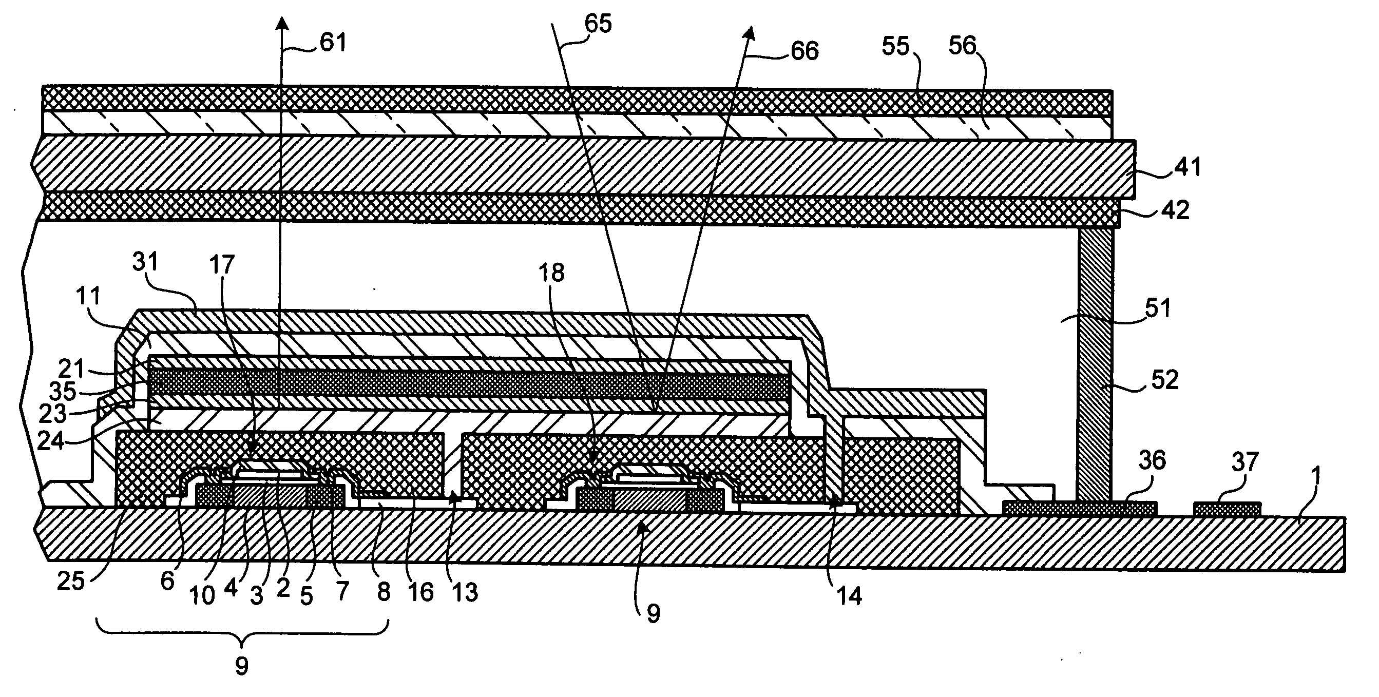
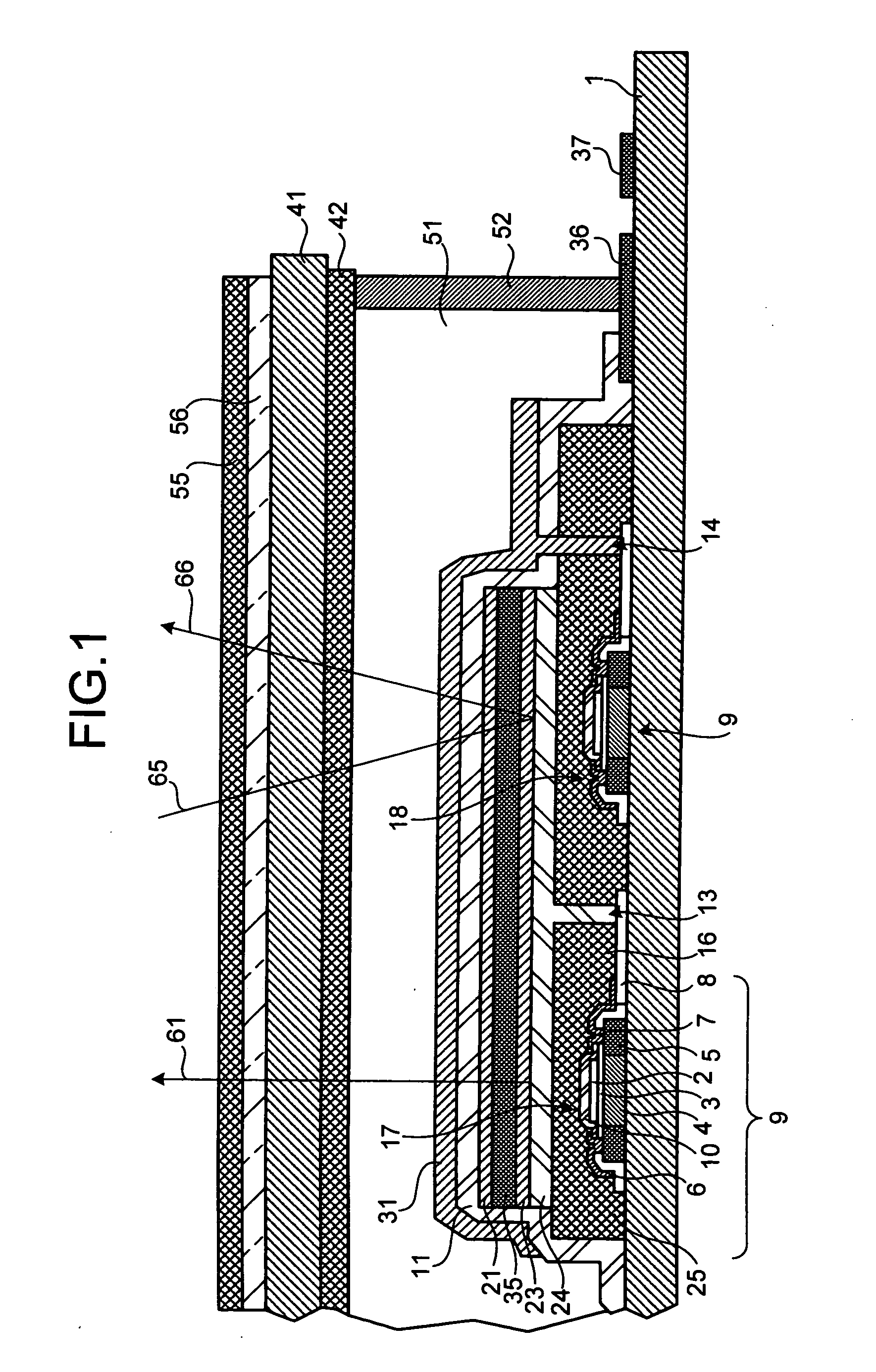
[0094] Thus, in the first embodiment, such a constitution is employed that the EL control switching element 17 and the liquid crystal layer switching element 18 are provided on the first substrate 1 and both the switching elements 17 and 18 are covered with the cathode electrode 24 of the EL element 33. Therefore, these switching elements 17 and 18 do not block the EL element 33. Accordingly, a bright EL element 33 can be obtained.

[0095] Further, because the reflectivity of the cathode electrode 24 is utilized as the reflective electrode, the reflective electrode of the liquid crystal display element is not blocked by the EL control switching element 17 and the liquid crystal layer switching element 18. Accordingly, bright reflective display from the liquid crystal display element can be made possible.

[0096] When displaying is performed by light emission of the EL element 33, the polarizing film 55 and the retardation film 56 prevent reflective light at the cathode electrode 24 ser...

second embodiment

[0104] The liquid crystal layer 51 sealed between the first substrate 1 and the second substrate 41 is diffusing type liquid crystal obtained by mixing liquid crystal molecules and transparent solid material made from acrylic resin of organic polymer material. The acrylic resin is illustratively made from transparent solid material of a porous body, and modules diffuse and penetration by applying a voltage to the liquid crystal layer 51. The liquid crystal molecule has a refractive index (no) corresponding to normal light and a refractive index (ne) corresponding to abnormal light. A transparent state and a diffused state of liquid crystal occur depending on a differentiation between the refractive index (np) of the transparent solid material and the refractive indexes (no and ne) of liquid crystal molecule and orientation of the liquid crystal molecule. In the second embodiment, PNM-157 manufactured by Dainippon Ink And Chemicals, Incorporated is uses as material for the liquid cry...

third embodiment

[0117] An insulating film for protection 11 is provided on the EL element 33 to prevent moisture from penetrating the EL element 33 and prevent the EL element 33 from degrading at subsequent steps. To reduce the step occurring due to the switching elements 17, 18, and the EL element 33, an EL step planarizing film 26 made from acrylic resin is provided on the insulating film for protection 11. In the third embodiment, the planarization of the EL step planarizing film 26 is comprehensively performed by performing polishing step after acrylic resin formation. Then, a display electrode 31 is formed on the planarized EL step planarizing film 26.

[0118] An LC connecting opening 14 for electrically connecting the drain electrode 7 of the liquid crystal layer switching element 18 and the display electrode 31 constituting a liquid crystal display pixel via the drain connecting electrode 8 is formed in the EL step planarizing film 26. The display electrode 31 is electrically connected to the ...


PUM

PropertyMeasurementUnit
twist angleaaaaaaaaaa
refractive indexaaaaaaaaaa

Abstract

An EL element (33) is provided on a first substrate (1) to make it possible to perform both light emission display according to the EL element (33) and reflective display according to a liquid crystal display element. An EL control switching element (17) and a liquid crystal layer switching element (18) are provided on a face of the first substrate (1) positioned on the side of a liquid crystal layer (51). The EL control switching element (17) is connected to an anode electrode (21) or a cathode electrode (24) constituting the EL element (33). By connecting the liquid crystal layer switching element (18) to a display electrode (31) and a reflective electrode (28) constituting a liquid crystal display element, a liquid crystal display element and a light emitting element are integrated in a liquid crystal display device incorporated with the liquid crystal display element therein, so that thinning and weight reduction are achieved considering electrical connection therebetween and both reflective display and transmissive display are made possible.

Description

TECHNICAL FIELD [0001] The present invention relates to a liquid crystal display device that incorporates an electroluminescent element (hereinafter, “EL element”) as a light source or a display element therein, and in particular to a liquid crystal display device usable as a reflective liquid crystal display device when the EL element is off. BACKGROUND ART [0002] Transmissive-type liquid crystal display devices, in which the liquid crystals themselves do not emit light, performs displaying with transmitted light from a light source provided in the device are typically used in small-sized information apparatuses or the like. Apart form the transmissive-type liquid crystal display device, reflective liquid crystal display devices are known that utilizes reflected light of light entering in a liquid crystal display panel externally to perform displaying. Moreover, transflective-type liquid crystal display devices are known as having both functions of transmissive type and reflective ...

Claims


Application Information

Patent Timeline
Patent Type & Authority Applications(United States)
IPC IPC(8): G02F1/135G02F1/1335G09G3/32G09G3/36
CPCG02F1/1335G02F2001/133342G09G3/3208G09G3/36G09G3/3611G09G3/3648G09G2300/046G09G2300/08G02F1/133342
Inventor SEKIGUCHI, KANETAKA
Owner CITIZEN WATCH CO LTD
Why Eureka
Try Eureka