System and method for measuring tip velocity of sprayed fuel
- Summary
- Abstract
- Description
- Claims
- Application Information
AI Technical Summary
Benefits of technology
Problems solved by technology
Method used
Image
Examples
Embodiment Construction
[0022] A preferred embodiment of the present invention is described with reference to accompanying drawings below.
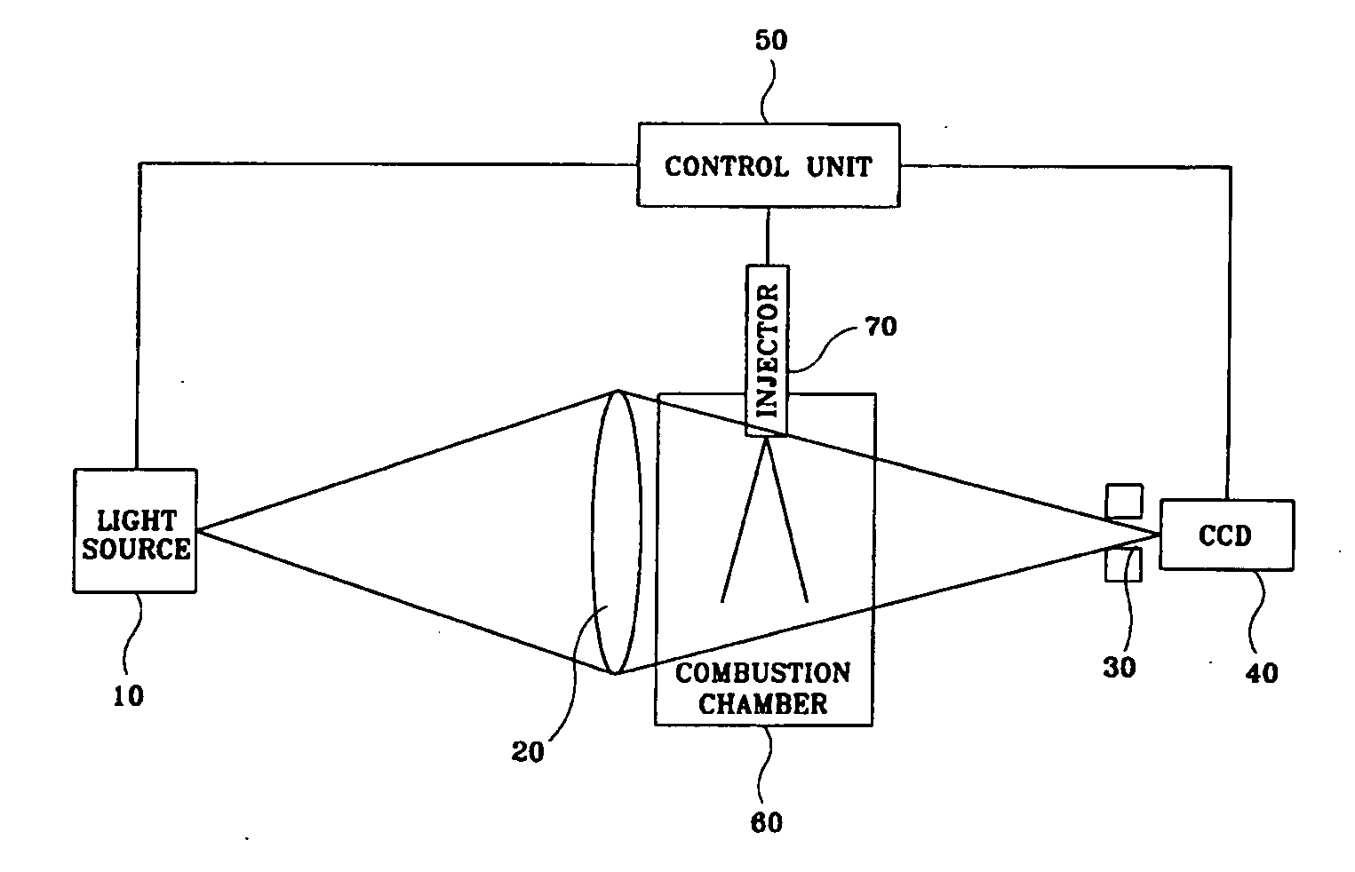
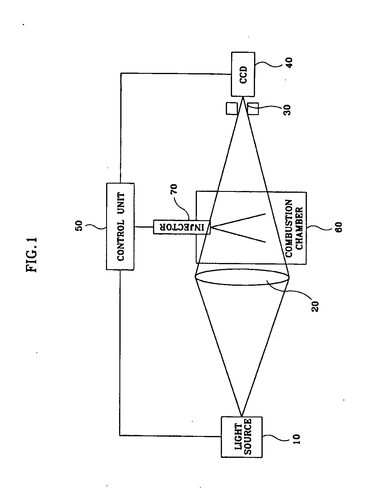
[0023] As shown in FIG. 1, the system for measuring the tip velocity of sprayed fuel in an engine according to the present invention includes a light source 10, a lens 20, a pinhole 30, a CCD camera 40, and a control unit 50.
[0024] The light source 10 emits light under the control of the control unit 50, and the lens 20 is a convex lens that is located between the light source 10 and a combustion chamber 60 to condense the light emitted from the light source 10 and allow the condensed light to enter into the combustion chamber 60. That is, the distortion of an image occurs when the lens 20 is installed between the combustion chamber 60 and the CCD camera 40, so that the lens 20 is installed between the light source 10 and the combustion chamber 60 to prevent the distortion.
[0025] The pinhole 30 is located between the combustion chamber 60 and the CCD camera 40 to elim...
PUM
 Abstract
Description
Claims
Application Information
 - R&D
- Intellectual Property
- Life Sciences
- Materials
- Tech Scout
- Unparalleled Data Quality
- Higher Quality Content
- 60% Fewer Hallucinations
Browse by: Latest US Patents, China's latest patents, Technical Efficacy Thesaurus, Application Domain, Technology Topic, Popular Technical Reports.
© 2025 PatSnap. All rights reserved.Legal|Privacy policy|Modern Slavery Act Transparency Statement|Sitemap|About US| Contact US: help@patsnap.com


