Method and apparatus for optically controlling the quality of objects having a circular edge

a technology of optical control and object, applied in the field of optically testing the quality of objects, can solve the problems of barely reproducible and high risk of errors in merely visual inspection of the edge region for quality by an operator, and achieve the effect of increasing sensitivity and not reducing throughpu

Inactive Publication Date: 2006-04-06
MICRO EPSILON MESSTECHNIK GMBH & CO KG
View PDF21 Cites 79 Cited by
  • Summary
  • Abstract
  • Description
  • Claims
  • Application Information

AI Technical Summary

Benefits of technology

[0030] To be able to examine the complete edge of a wafer while gripping its edge, two sequential measurements are needed. Between the two measurements, the wafer is gripped again in a different location, so that it is possible to inspect in the second measurement regions that were covered by the handling during the first measurement. With a measuring time of less than 15-20 seconds for every 300 mm of wafer—without regripping, i.e., regions that are possibly covered by the handling of the wafer are treated as exclusion zone—or a measuring time of less than 30-40 seconds per wafer—including regripping and measurement of the regions that were covered by the handling during the first rotation of the wafer—while excluding each time the robot handling for supplying the wafer, the throughput of the system is oriented toward the practical use in the production, which handles 60 or more wafers per hour. It follows from these requirements as to the throughput that the exposure time for taking one scanning line is in a range of a few microseconds, and that thus special requirements must be met as to the sensitivity of the linear-array cameras in use, the light intensity of the optical imaging system, and the intensity of the sources of illumination. For such short integration times, the use of highly sensitive time delay integration (TDI) sensors has been found advantageous on the part of the linear-array cameras. Unlike conventional linear-array cameras, same use a plurality of parallel arranged indiv

Problems solved by technology

Moreover, it has been found that the currently, merely visual inspection of the edge re

Method used


Image

  • Method and apparatus for optically controlling the quality of objects having a circular edge
  • Method and apparatus for optically controlling the quality of objects having a circular edge
  • Method and apparatus for optically controlling the quality of objects having a circular edge

Examples


Embodiment Construction

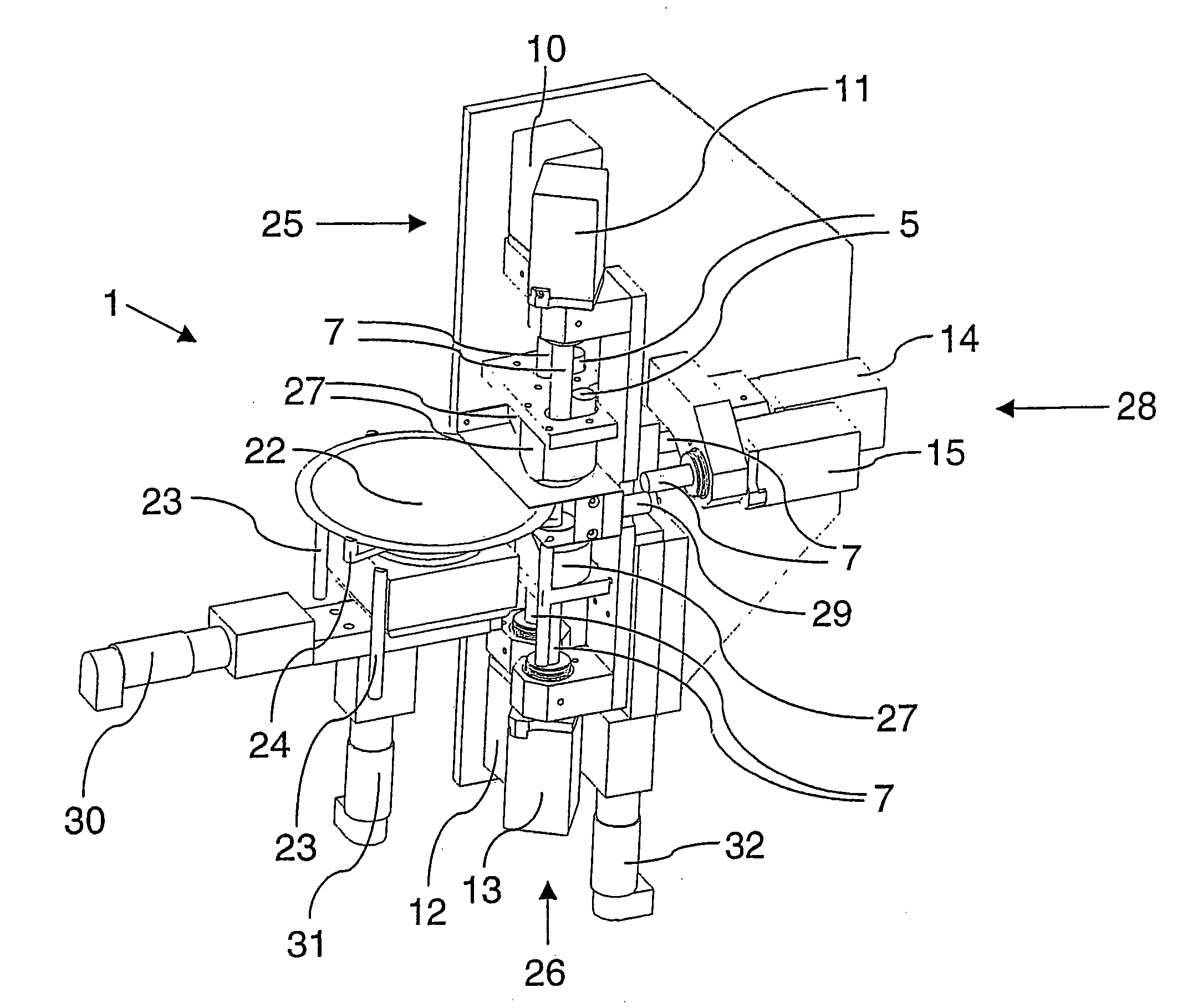
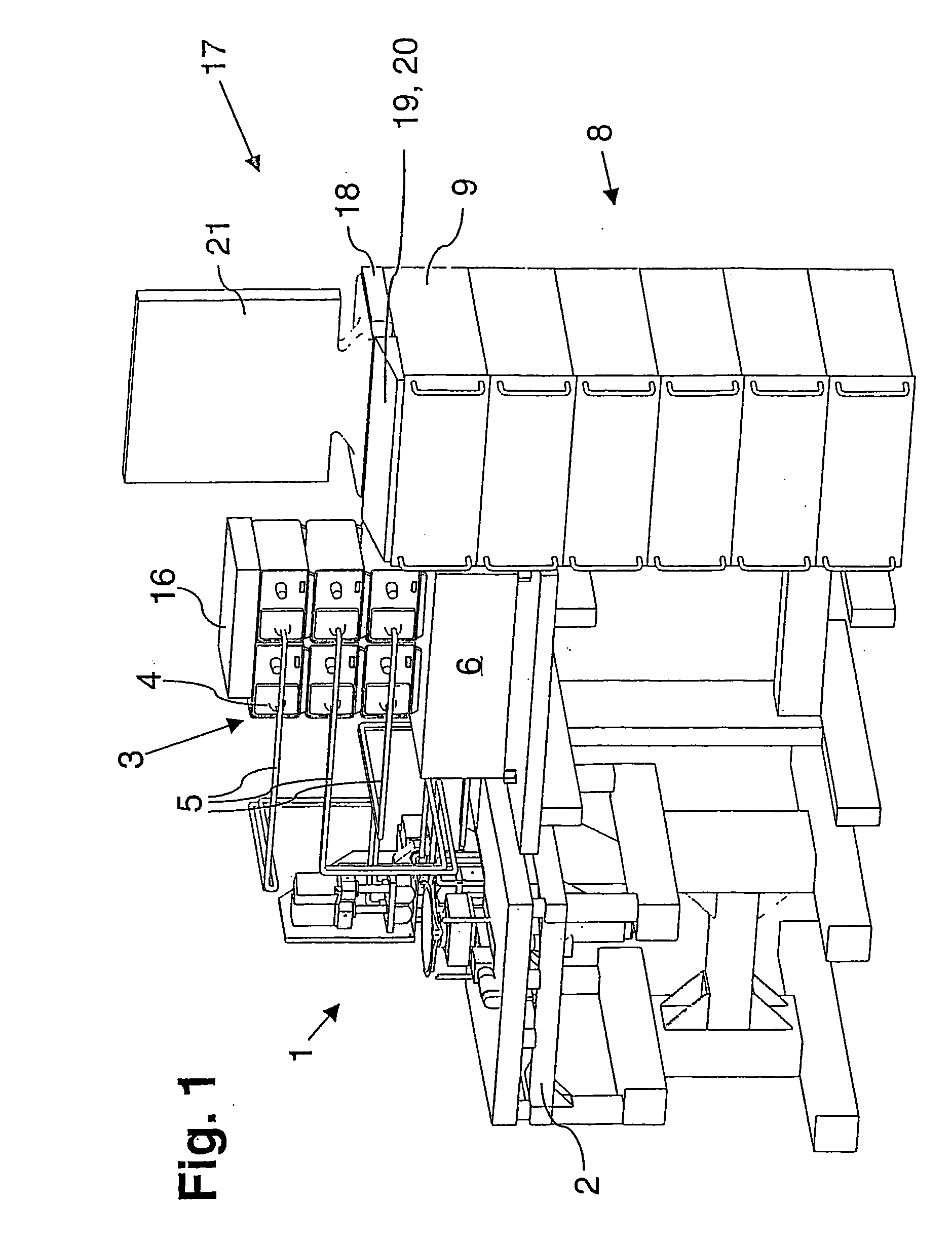
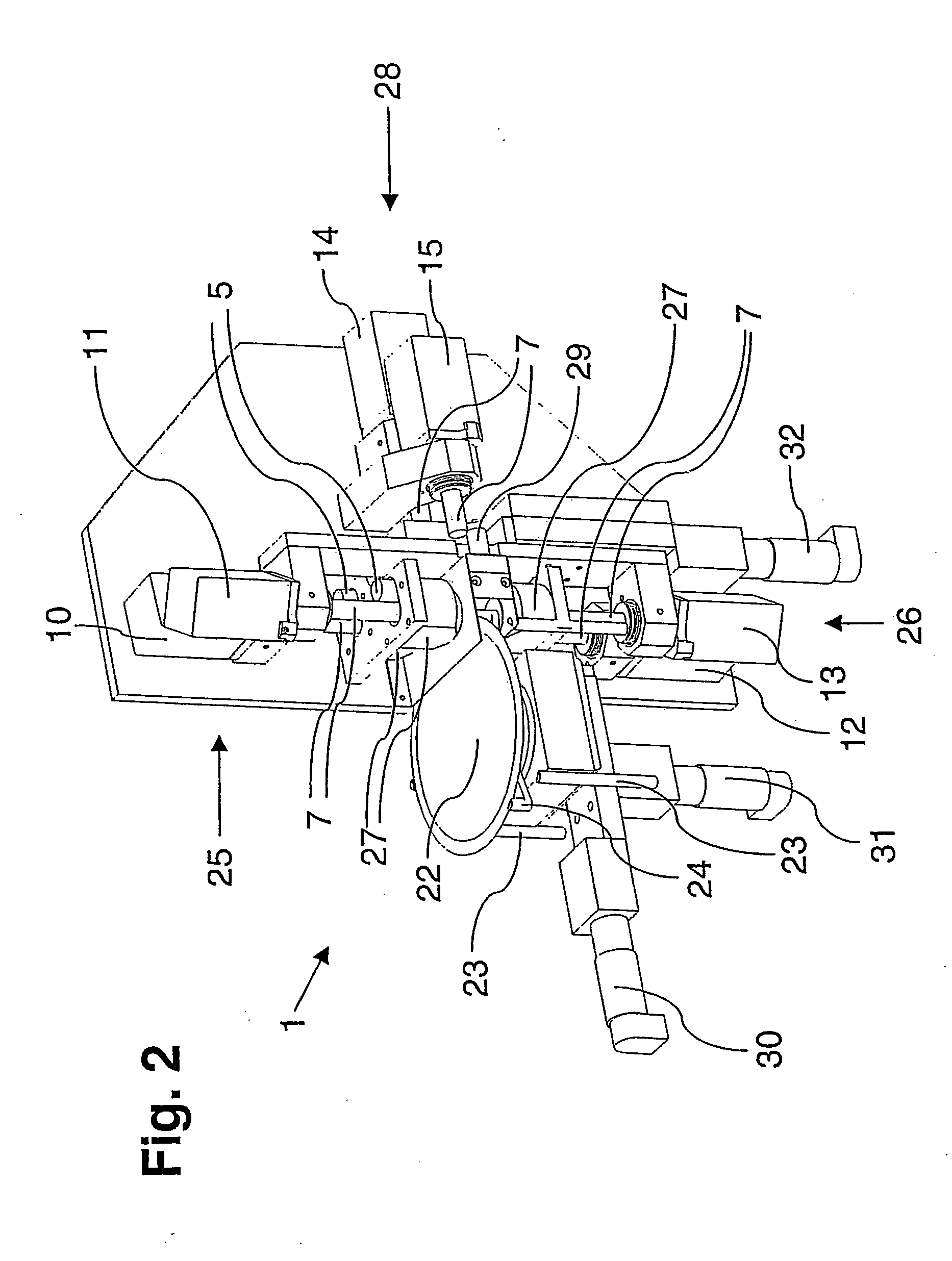
[0044] Referring more particularly to the drawings, the apparatus of the invention comprises a measuring unit 1, which is described in greater detail below, and which is arranged on a base 2 that is supported as much as possible in a vibration free manner. Besides the base 2, an illumination unit 3 is provided, which comprises a total of six high-output cold-light sources 4. To each light source 4, a light guide 5 is associated, which supplies the light of the light sources 4 to the measuring unit 1. Below the illumination unit 4, an amplifier unit 6 is provided for a motor-operated activation to readjust the properties of optical imaging systems 7 of the measuring unit 1 (see FIG. 2) in the sense of a vario-focus.

[0045] An evaluation unit 8 is also provided which comprises a total of six industrial evaluation PCs 9. The PCs 9 are associated to a total of six camera systems 10, 11, 12, 13, 14, 15 such that respectively one PC 9 processes the measured data of one camera system 10-15...


PUM


Abstract

Method and apparatus for optically testing the quality of objects such as silicon wafers which have a circular peripheral edge, wherein light is directed onto the edge region of the object, and the light radiating from the object due to reflection, refraction and/or diffraction is detected by means of a measuring unit which produces an image from the received light. Defects on and/or in the object are identified from the produced image.

Description

CROSS REFERENCE TO RELATED APPLICATION [0001] The present application is a continuation of international application PCT / DE2004 / 000474, filed 10 Mar., 2004, and which designates the U.S. The disclosure of the referenced application is incorporated herein by reference.BACKGROUND OF THE INVENTION [0002] The invention relates to a method for optically testing the quality of objects which normally have a circular edge, wherein light is directed to the edge of the object. Furthermore, the invention relates to an apparatus for optically testing the quality of such objects, in particular for carrying out the method of the invention, with at least one light-emitting illumination unit for illuminating the edge of each object. [0003] Methods and apparatus of the type under discussion have been known from practical operation for a long time, and they play a more and more important role within the scope of a complete inspection of objects, in particular products of industrial production. These ...

Claims


Application Information

Patent Timeline
IPC IPC(8): G01N21/88G01N21/95
CPCG01N21/9503
Inventor WAGNER, ROBERT
Owner MICRO EPSILON MESSTECHNIK GMBH & CO KG
Why Eureka
Try Eureka