Automated visual inspection system for the detection of microbial growth in solutions

a visual inspection system and solution technology, applied in the field of automatic visual inspection system for the detection of microbial growth in solutions, can solve the problems of limited sensitivity and the need to interpret the probability of the results obtained, and the future use of the investigator's tool may very well shrink, so as to achieve the effect of reducing the radiant energy of the illumination system, facilitating adjustment, and enhancing the optical density of contaminating materials

Active Publication Date: 2006-04-06
BUDD GERALD WALTER +1
View PDF1 Cites 37 Cited by
  • Summary
  • Abstract
  • Description
  • Claims
  • Application Information

AI Technical Summary

Benefits of technology

[0044] With said detector being mounted inside a sealed enclosure the critical optical components of the system can be protected from the environment. The detector is mounted in such a manner so that so that the optical path can be easily adjusted with the target area. The design of the sensor enclosure allows for the insertion of optical filter elements within the optical path of the invention.
[0045] Contaminating materials with less optical density can be enhanced in the image by reducing the radiant energy of the illumination system. The illumination system provides a means of stable uniform light that can be used for an opacity measurement of the solution. A clear solution will attenuate the light less than that of a torpid solution. In the case of media fill samples the opacity of the solution can be monitored over a period of time and small changes in the opacity can be measured and recorded. Over time a baseline for a specific product will be established and any deviation from the nominal opacity can be measured. The media fill samples will be labeled with a unique identification via 2-D bar code or human readable code that can be read electronically. The media fill samples can then be tracked (electronically) at the time of each inspection and any change in the contents can be measured and recorded.

Problems solved by technology

The use of the Attribute Sampling Inspection Tables with raw visible particle inspection data results in the incorrect rejection of good batches and incorrect acceptance of undesirable batches.
Although the use of Attribute Sampling Assay Tables can be made compatible with raw visible inspection data, its limited sensitivity and the need to interpret the probability of the results obtained may very well shrink its future use to that of an investigators tool.
The technology allowed the system to identify heavy contaminating particles resting of the bottom of container, something that was not possible using previous technology.

Method used


Image

  • Automated visual inspection system for the detection of microbial growth in solutions
  • Automated visual inspection system for the detection of microbial growth in solutions
  • Automated visual inspection system for the detection of microbial growth in solutions

Examples


Embodiment Construction

[0059] The invention is a combination of mechanical, electronic, and software components configured in the proper way to produce information that will yield repeatable measurement results.

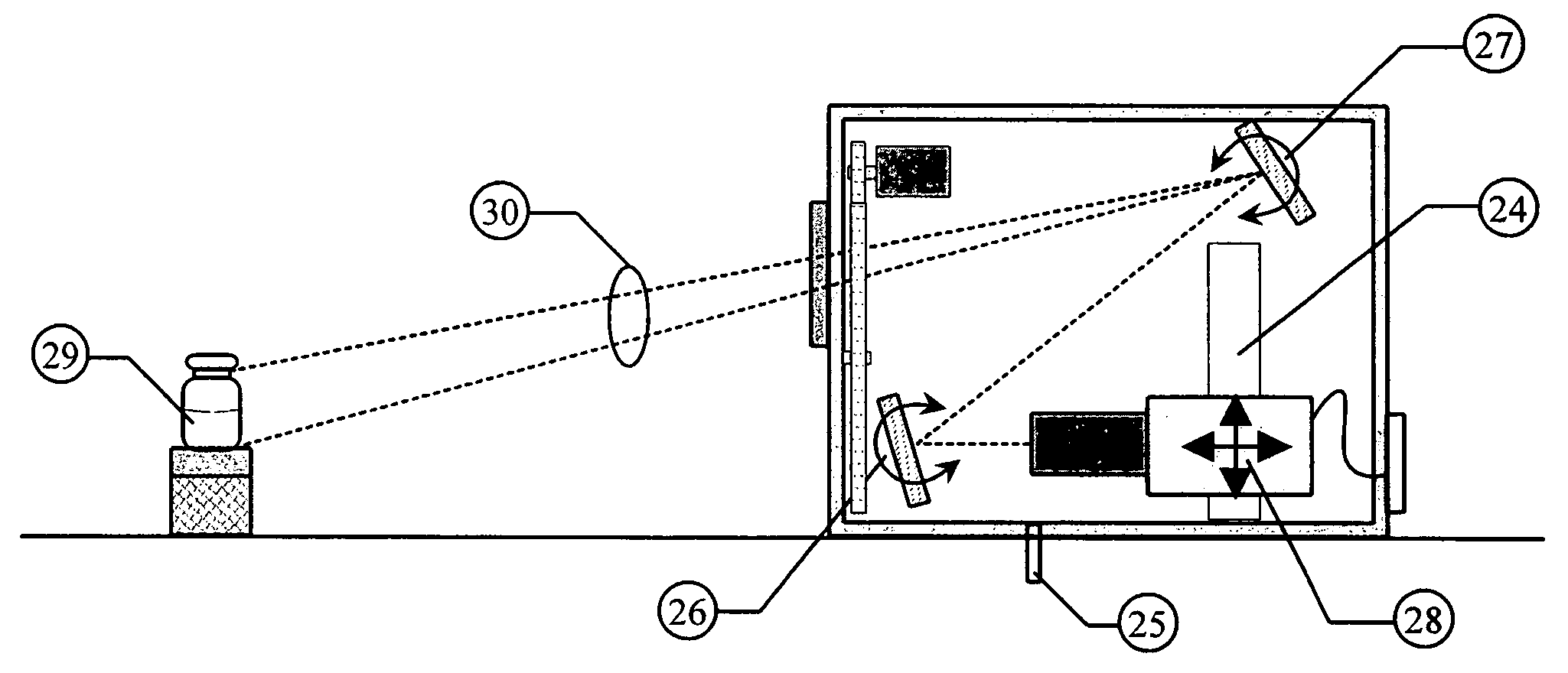
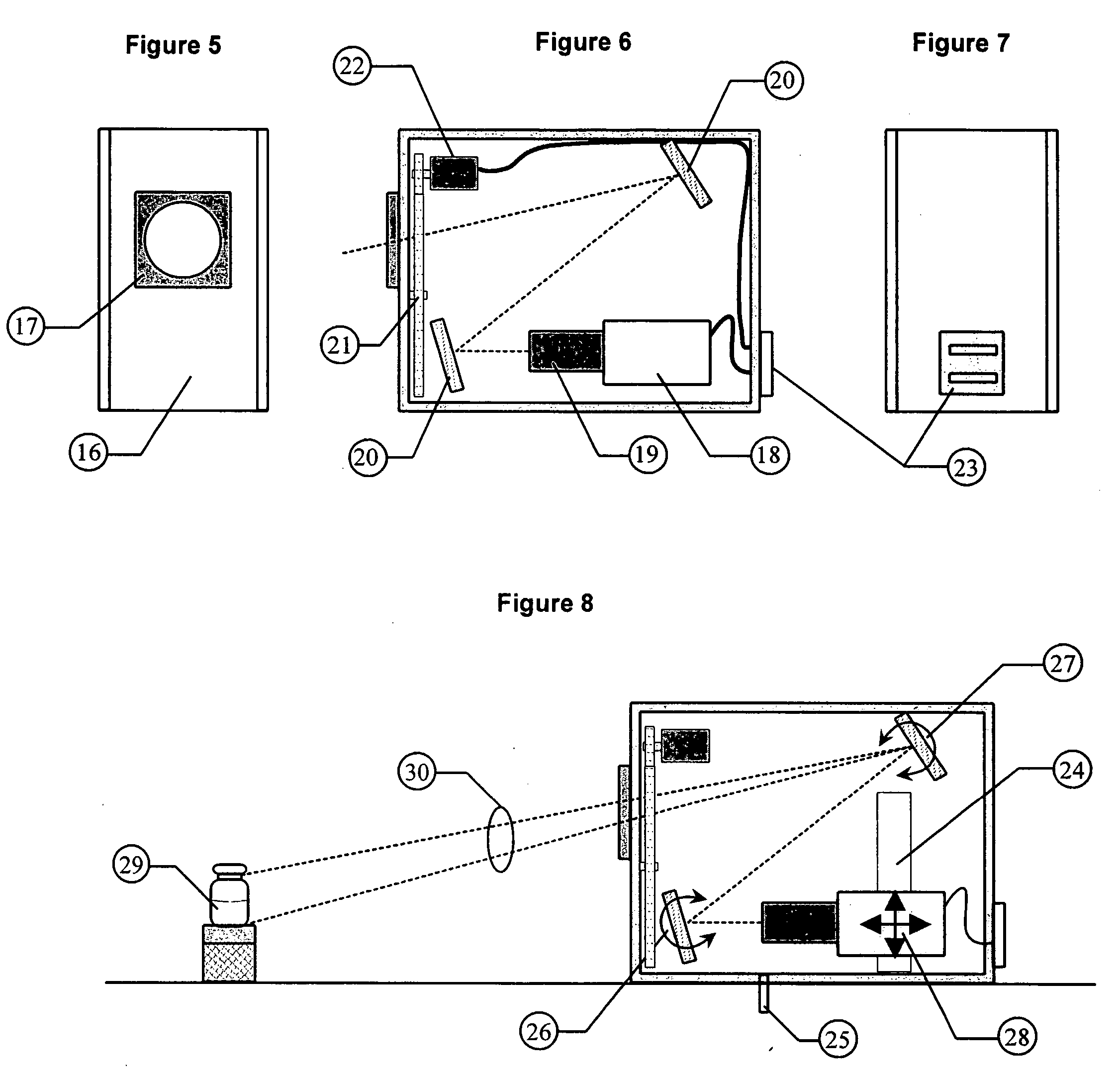
[0060] The basic components of this invention have been described in detail in U.S. patent application “An NIST Traceable Automated Inspection System for an inspection of particles in solution” (Ser. No. 10 / 981,801 filed on Nov. 5, 2004) and U.S. patent application “Small container fluid dynamics to produce optimized inspection conditions” (Ser. No. 11 / 076,375 filed on Mar. 9, 2005). The components used are essentially the same except that the software and optimized motion profile (spin conditions) have been modified to extract information relative to the detection of microbial growth in media solutions. The figures are provided here to illustrate relative position of key components used in the present invention.

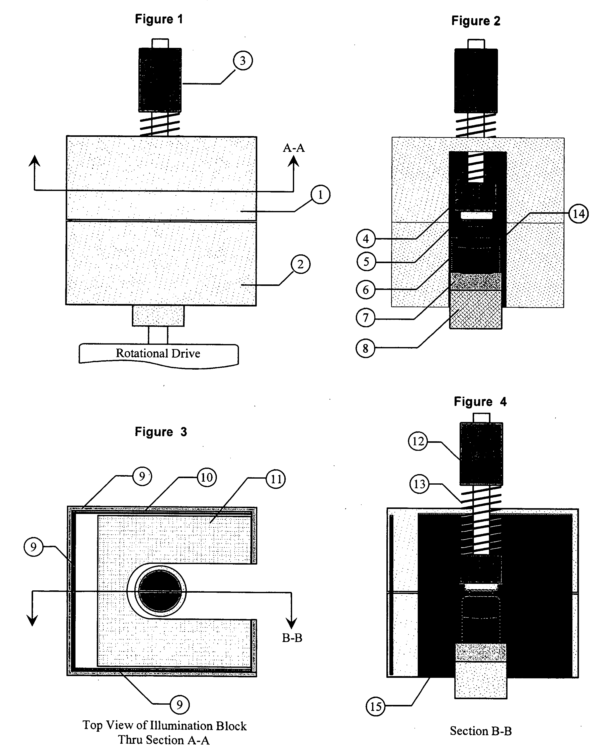
[0061] The first key component is a unique illumination system designed to provide a ...


PUM

PropertyMeasurementUnit
diameteraaaaaaaaaa
diameteraaaaaaaaaa
diameteraaaaaaaaaa

Abstract

Essential prerequisites for any injectable product are its sterility, its freedom from pathogens and its freedom from visible particle contamination . . . . These requirements must be satisfied prior to the release of an injectable product batch for sale and use. A major difficulty in responding to these assay requirements is the need for a size sensitivity difference of 100 or greater in determining the presence of viable pathogenic organisms and of non-viable random particle contaminants. The wide dynamic testing range cannot be satisfied in current art with a single non-destructive testing station. The present invention uses a special agitation procedure to generate separate liquid volumes containing the small viable and larger non-viable particle contaminants. This separation makes possible the introduction of sensing systems that have been optimized for each size range and that can operate in parallel without interference.

Description

CROSS-REFERENCE TO RELATED APPLICATIONS [0001] I claim priority to my Provisional Patent Application No. 60 / 615,981 with filing date Oct. 5, 2004.DESCRIPTION [0002] 1. Field of the Invention [0003] This invention relates to the procedures and devices utilized in the optical inspection of transparent containers for the presence of contaminating microbial growth in media fill, contaminating particulate matter and particularly to inspection of injectable pharmaceutical preparations. [0004] 2. Background of the Invention [0005] The inspection for and elimination of visible particle contaminated containers from a batch of injectable pharmaceuticals is a United States Pharmacopeia requirement. This inspection is specified to be, whenever possible, after the product is in its final container. Evaluation that the visible particle incidence rate is within USP acceptance limits for human or veterinary use is an essential part of the injectable batch release procedure. It is also an essential ...

Claims


Application Information

Patent Timeline
Patent Type & Authority Applications(United States)
IPC IPC(8): G01N21/90
CPCG01N15/042G01N15/1463G01N21/9027G01N2015/1486G01N2015/1493
Inventor BUDD, GERALD WALTERKNAPP, JULIUS Z.
Owner BUDD GERALD WALTER
Why Eureka
Try Eureka