Wire grid polarizer and fabrication method thereof

a polarizer and wire grid technology, applied in the field of optical devices, can solve the problems of generating reflection loss corresponding to approximately 4%, taking a lot of time and cost to form multi-layer anti-reflection coatings, and enhancing visible light transmittance, so as to achieve easy fabrication, and enhance visible light transmittance

Inactive Publication Date: 2006-04-06
LG ELECTRONICS INC
View PDF12 Cites 35 Cited by
  • Summary
  • Abstract
  • Description
  • Claims
  • Application Information

AI Technical Summary

Benefits of technology

[0014] Therefore, an object of the present invention is to provide a wire grid polarizer capable of enhancing a visible light transmittance.
[0015] Another object of the present invention is to provide a method for easily fabricating a wire grid polarizer capable of enhancing a visible light transmittance.

Problems solved by technology

Since the multi-layer anti-reflection coatings are formed by a vacuum deposition technique, it takes a lot of time and costs to form the multi-layer anti-reflection coatings.
As aforementioned, the related art wire grid polarizer has the problem that a reflection loss corresponding to approximately 4% is generated.
Since the multi-layer anti-reflection coatings are formed by a vacuum deposition technique, it takes a lot of time and costs to form the multi-layer anti-reflection coatings.

Method used


Image

  • Wire grid polarizer and fabrication method thereof
  • Wire grid polarizer and fabrication method thereof
  • Wire grid polarizer and fabrication method thereof

Examples


Embodiment Construction

[0029] Reference will now be made in detail to the preferred embodiments of the present invention, examples of which are illustrated in the accompanying drawings.

[0030] Hereinafter, a wire grid polarizer capable of enhancing a visible light transmittance and a fabrication method thereof capable of simplifying processes will be explained in more detail with reference to FIGS. 2 to 6.

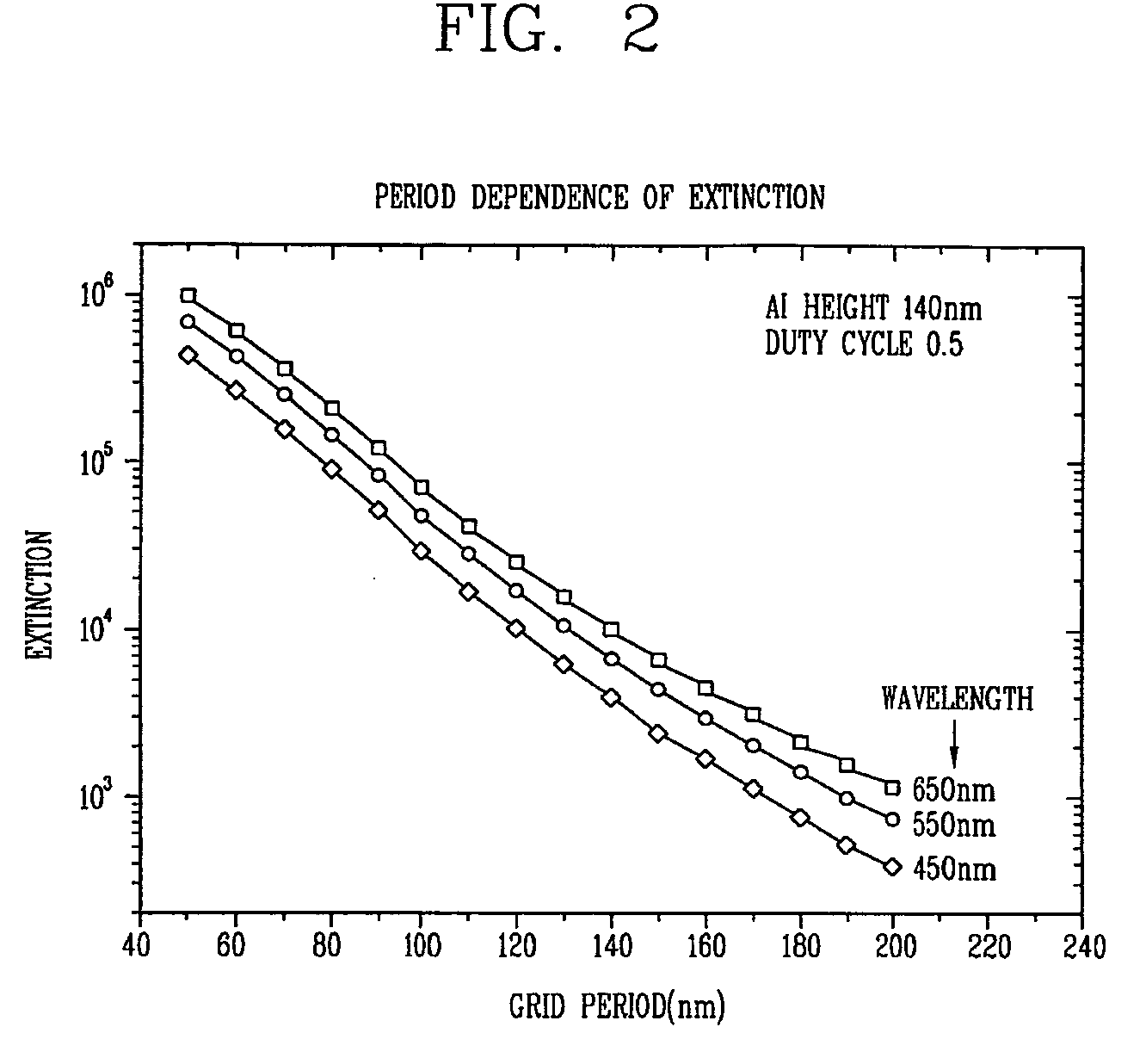
[0031]FIG. 2 is a graph showing a relation between a grid period and a polarization extinction ratio of a wire grid polarizer according to the present invention.

[0032] As shown in FIG. 2, metallic wires of the wire grid polarizer according to the present invention are formed of aluminum, and each metallic wire has a height of 140 nm. Under an assumption that each of the metallic wires has a width corresponding to a half of a grid period (the grid period has to be less than a half of a wavelength of an incident light beam), a polarizing efficiency is increased as the grating period becomes shorter. For ...


PUM


Abstract

A wire grid polarizer capable of increasing a visible light transmittance and a fabrication method thereof. The wire grid polarizer comprises a substrate having a first surface and a second surface, a plurality of metallic wires formed on the first surface, and grating patterns formed on the second surface and having a grating period shorter than a half of a wavelength of an incident light beam.

Description

[0001] Pursuant to 35 U.S.C. § 119(a), this application claims the benefit of earlier filing date and right of priority to Korean Patent Application No. 79683 / 2004, filed Oct. 6, 2004, the content of which is hereby incorporated by reference herein in its entirety. BACKGROUND OF THE INVENTION [0002] 1. Field of the Invention [0003] The present invention relates to an optical device, and more particularly, to a wire grid polarizer and a fabrication method thereof. [0004] 2. Description of the Prior Art [0005] Generally, a wire grid polarizer for polarizing an incident light beam in accordance with the related art is composed of a plurality of parallel metallic wires formed on a transparent glass substrate. [0006]FIG. 1 is a view showing a structure of a wire grid polarizer in accordance with the related art. [0007] As shown in FIG. 1, the related art wire grid polarizer comprises a transparent glass substrate 10, and a plurality of parallel wires (11) (metallic grids) formed on the t...

Claims


Application Information

Patent Timeline
Patent Type & Authority Applications(United States)
IPC IPC(8): G02B5/30
CPCG02B5/3058
Inventor LEE, KI-DONG
Owner LG ELECTRONICS INC
Why Eureka
Try Eureka