Marine warning sign

a warning sign and marine technology, applied in the field of warning signs, can solve the problems of not being sufficiently rugged for the marine environment, posing a hazard to other vessels on the waterway, and overly-excessive power consumption, and achieve the effect of convenient application and low cos

Inactive Publication Date: 2006-04-06
DUNKLE THOMAS K +1
View PDF16 Cites 20 Cited by
  • Summary
  • Abstract
  • Description
  • Claims
  • Application Information

AI Technical Summary

Benefits of technology

[0017] To accomplish these objectives, a marine warning sign is provided which is comprised, in the preferred embodiment, of a sealed case, formed of a frame, a square rear panel and a square front panel assembly. The frame and the rear panel are fabricated of a corrosion resistant material, such as stainless steel. The front panel assembly is comprised first of a transparent material, such as an acrylic polymer. Under the transparent front panel is a non-transparent graphics panel. On the graphics panel some warning indicia are applied. Proximate to the edges of the graphics panel is a border formed by an electroluminescent tape,

Problems solved by technology

These vessels can potentially pose a hazard to other vessels on the waterway if the vessels under repair are not readily visible to other craft or vessels.
This may have potential application in the marine environment, but the invention, if used as a warning sign, must be switched manually and is not sufficiently rugged for the marine environment.
The means for illumination includes a neon bulb, which has an overly-excessive power consumption for the desired use of a marine warning sign.
Further, while it is portable, its means of se

Method used


Image

  • Marine warning sign
  • Marine warning sign
  • Marine warning sign

Examples


Embodiment Construction

[0025] The following discussion describes in detail one or more embodiments of the invention. The discussion should not be construed, however, as limiting the invention to those particular embodiments, and practitioners skilled in the art will recognize numerous other embodiments as well. The complete scope of the invention is defined in the claims appended hereto.

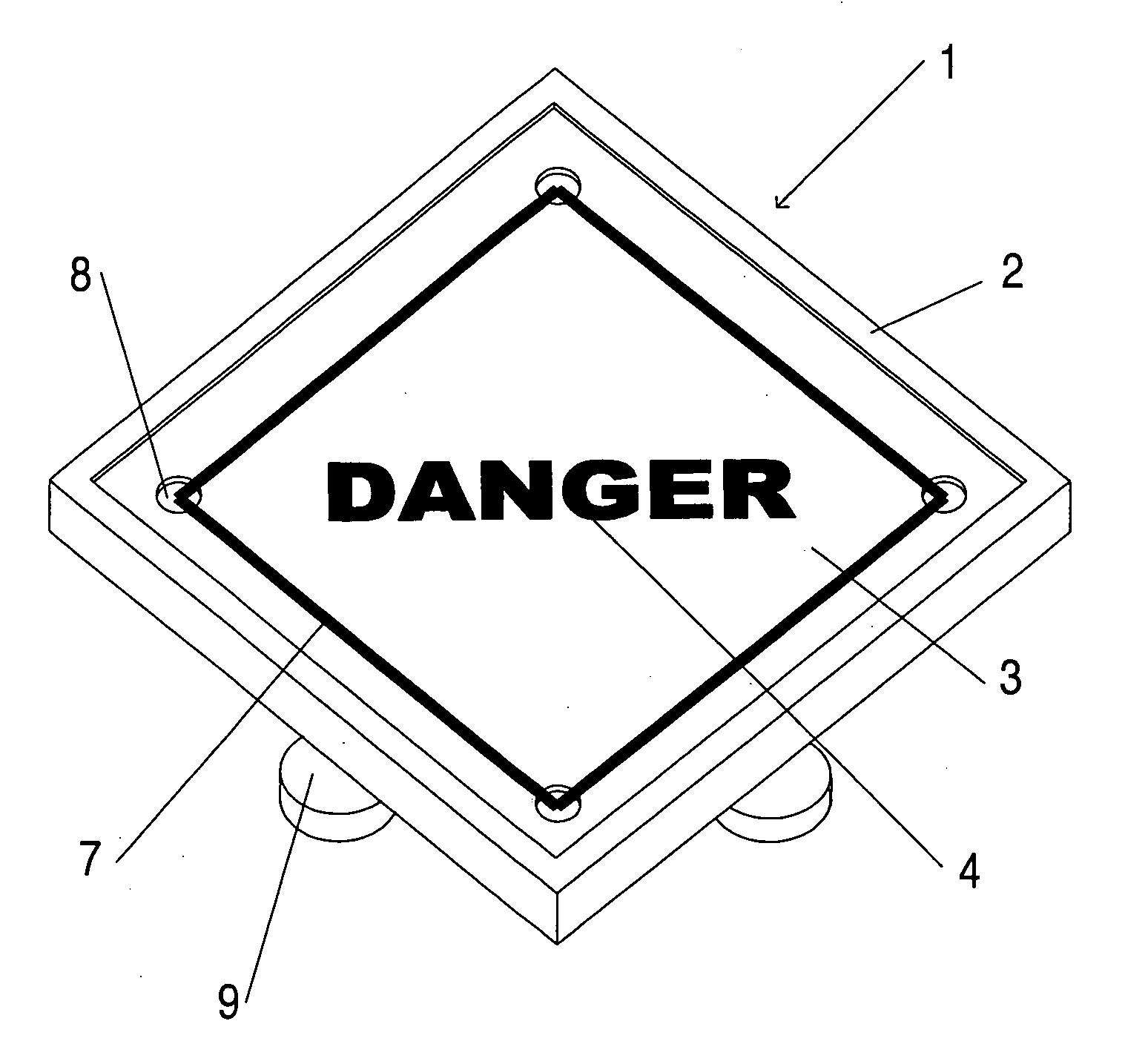
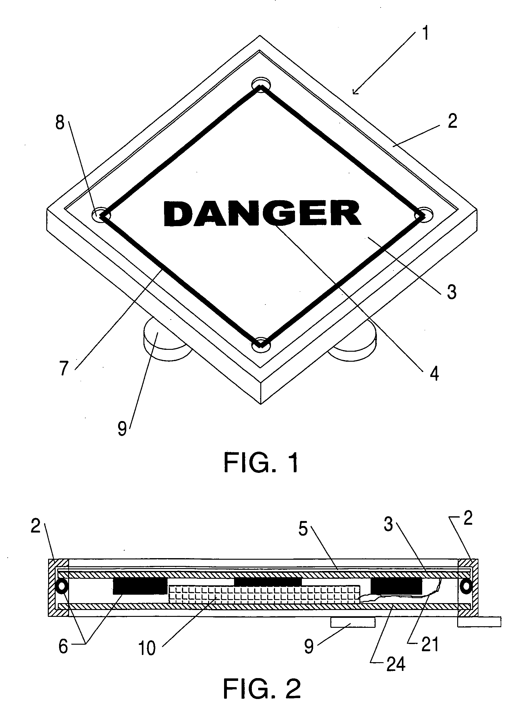
[0026] As shown in FIG. 1, the exterior of a marine warning sign 1 is in the form of a right prism, i.e., a shape in which the front and rear faces are square and are parallel and aligned to one another. The sides of the marine warning sign 1 are formed by a frame 2, comprised of four rectangular side panels, each panel having parallel lateral edges forming one edge of the front and rear faces, and parallel longitudinal edges, each of which are conjoined with a longitudinal edge of an adjacent side panel. In the preferred embodiment, the side panels of the frame 2 are mitered at 45 degree angles and conjoined to one anoth...


PUM


Abstract

A marine warning sign, in the shape of a right prism, having a frame forming a square of other polygonal shaped enclosure with straight sides and open front and rear faces. In the front face is positioned an assembly comprised of a transparent panel under which is a graphics panel. On the obverse face of the graphics panel is printed some desired warning indicia. A rear panel enclosed the rear face of the frame. A border, in the same shape as the frame, surrounds the indicia. The border is formed of electroluminescent tape. The electroluminescent tape illuminates when energized by an electrical power control located within the sign. The electrical power control is powered by a rechargeable battery which powers an a/c to d/c inverter. The electrical power control is switched on and off during night and day, respectively, by a circuit in the electrical power control comprised of a comparator having a bridge circuit with a photoresistor as one input. Mercury level switches also are provided to disable the electrical power control if the sign is tilted from its desired level attitude. The inverter provides alternating current to two leads of the electroluminescent tape, causing the electroluminescent tape to illuminate.

Description

BACKGROUND OF THE INVENTION [0001] 1. Field of the Invention [0002] The invention disclosed herein relates to a warning sign suitable for marine use [0003] 2. Description of the Prior Art [0004] In the maritime industry, particularly on the inland and intra-coastal waterways, vessels may be forced to temporarily anchor within the waterway for emergency repairs. These vessels can potentially pose a hazard to other vessels on the waterway if the vessels under repair are not readily visible to other craft or vessels. Graphical means for alerting other craft of an anchored or disabled vessel are desirous, which can provide warning under all conditions of daylight or night, which has its own power supply and which are portable and easily erected and stowed, and which are safe under potentially rough sea conditions. [0005] U.S. Pat. No. 6,247,700, issued to Procupetz on Jun. 19, 2001, discloses a light emitting shooting target using electroluminescent paint for greater illumination during...

Claims


Application Information

Patent Timeline
IPC IPC(8): F21V9/16
CPCB63B45/04B63B2201/08G09F13/22
Inventor DUNKLE, THOMAS K.DUNKLE, GREGORY D.
Owner DUNKLE THOMAS K
Why Eureka
Try Eureka