

Byte to byte alignment of multi-path data
- Summary
- Abstract
- Description
- Claims
- Application Information
AI Technical Summary
Benefits of technology
Problems solved by technology
Method used
Image

Examples
Embodiment Construction
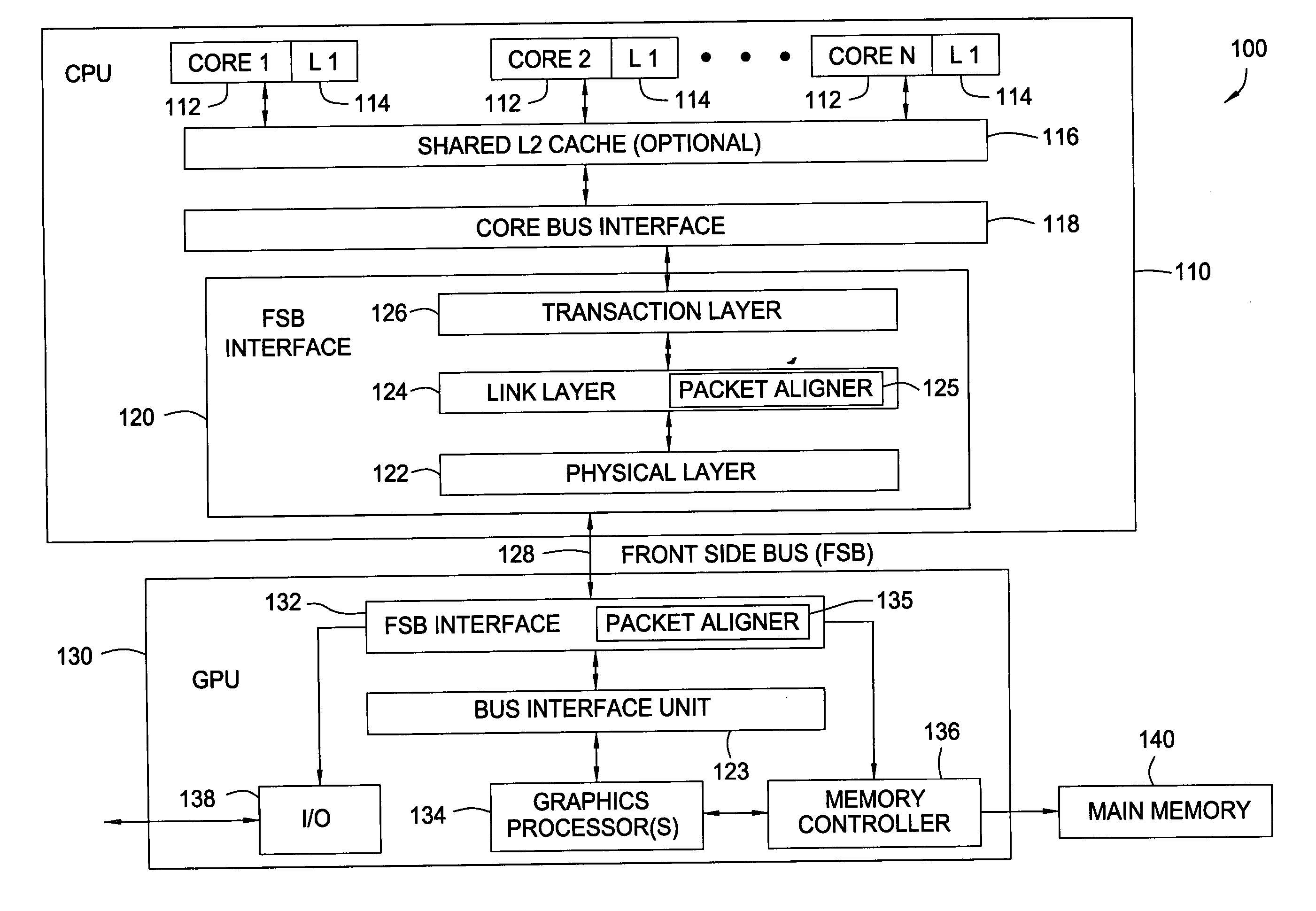
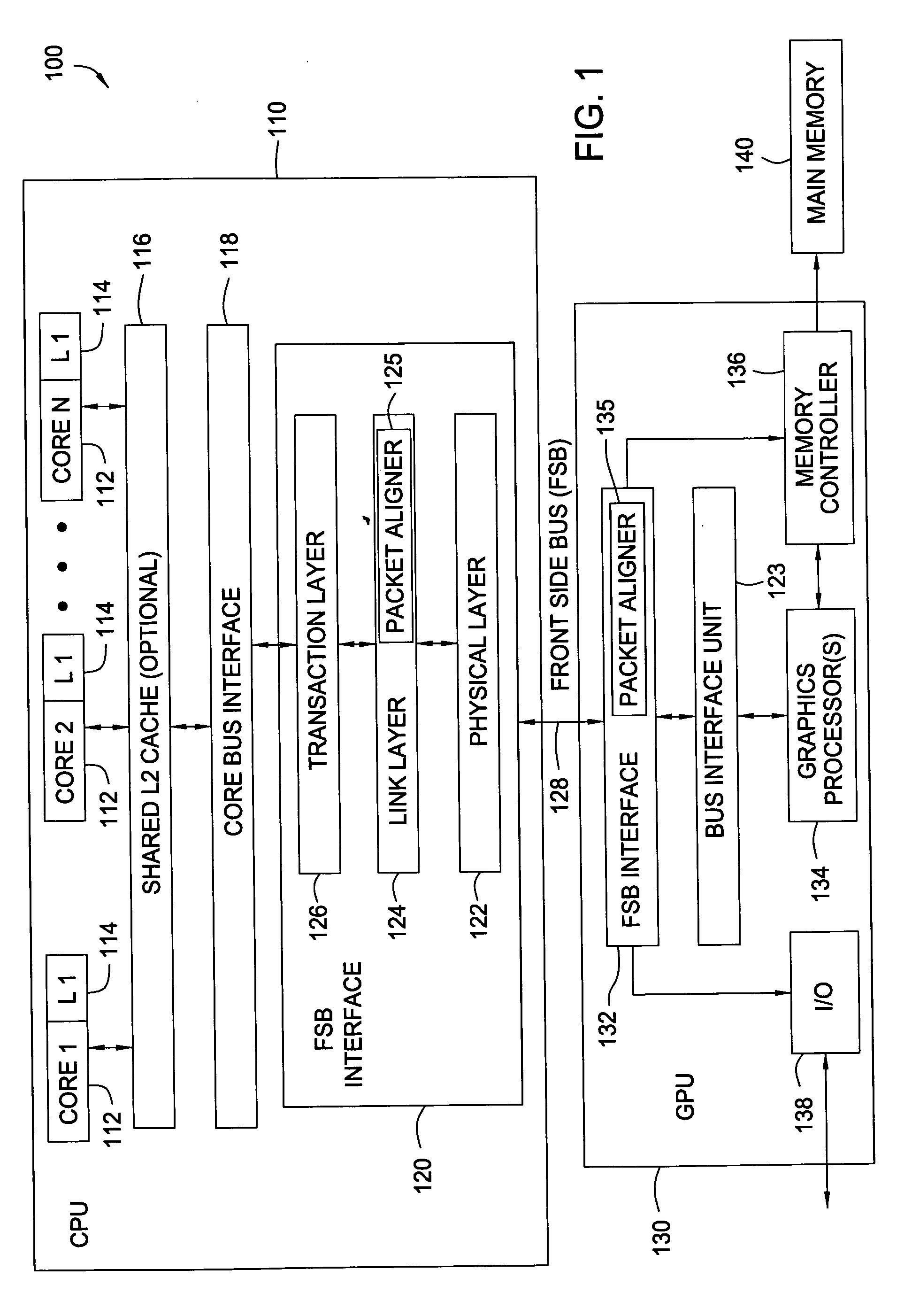
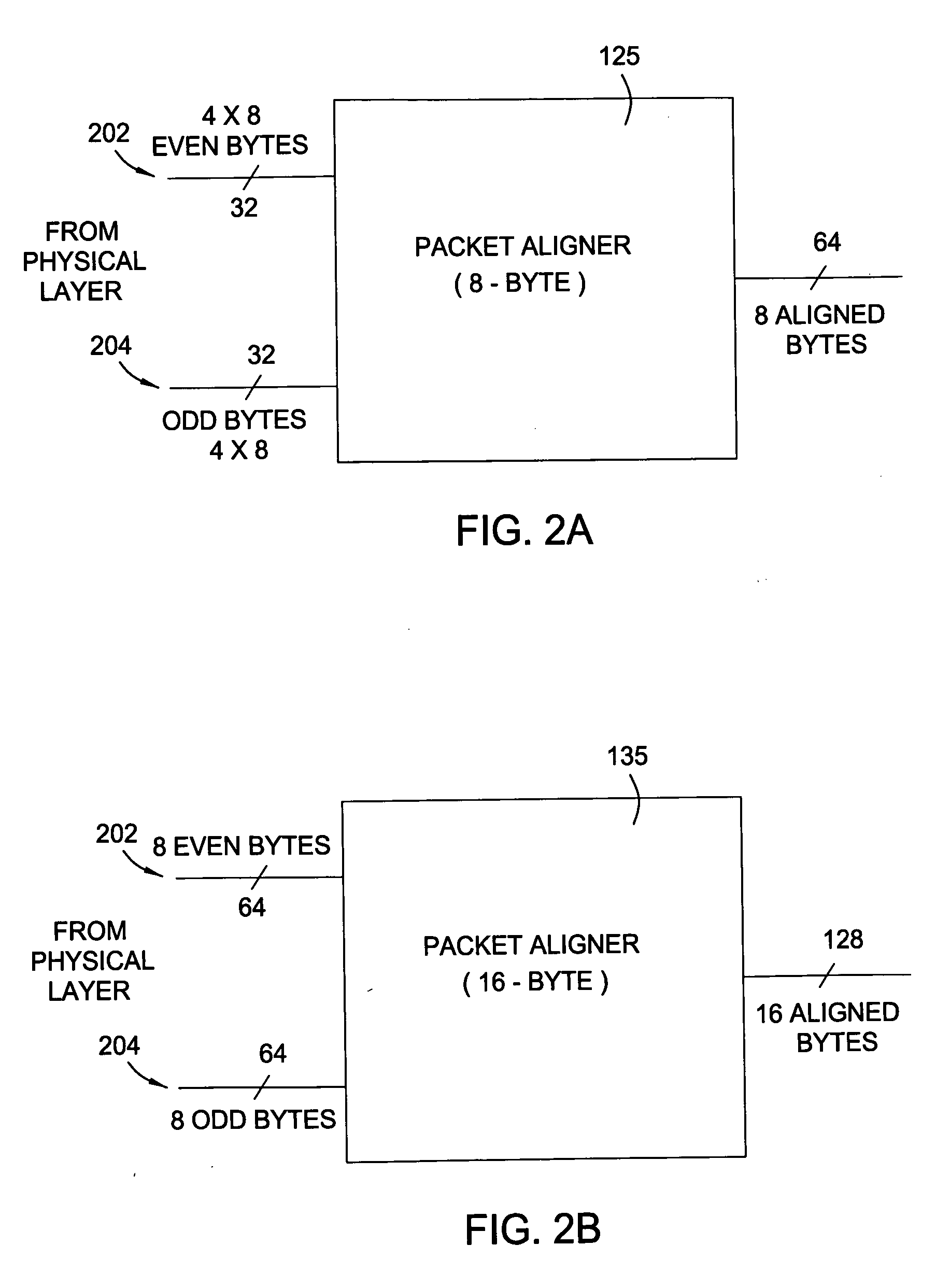
[0019] Embodiments of the present invention may be utilized in an effort to ensure bytes of data sequentially received on multiple single-byte data paths with properly aligned when presented on a multi-byte interface. A sufficient number of bytes received each channel may be stored (e.g., buffered) and examined to properly match data from each single-byte path. Once matched, the data may be output in a proper order on the multi-byte interface, for example, via some type of multiplexor arrangement. For some embodiments, alignment operations may be performed often (e.g., on a packet-by-packet basis) to compensate for various factors that may vary the skew between the multiple paths over time.
[0020] As used herein, the term data packet generally refers to any collection of data sent together, commonly between two devices and often with some type of header containing information about the data contained therein. While the size of a data packet may vary, it will typically (but not neces...
PUM
 Abstract
Description
Claims
Application Information