Remapping methods to reduce distortions in images

a technology of remapping and image, applied in the field of image remapping and drive remapping methods, can solve the problems of adding distortion to the image constructed by the scanning fiber device, adding distortion to the image, and reducing the effect of image distortion

Active Publication Date: 2006-04-06
UNIV OF WASHINGTON
View PDF55 Cites 127 Cited by
  • Summary
  • Abstract
  • Description
  • Claims
  • Application Information

AI Technical Summary

Benefits of technology

[0006] The present invention provides methods and systems for reducing the distortions in an image acquired or generated by a scanning beam device.
[0007] The methods of the present invention recognize that the distortions introduced into the images repeat for each scan pattern carried out by the scanning beam device. By calibrating and characterizing the actual scan pattern of the illumination spot generated by the scanning beam device, the present invention is able to compensate for the distortions caused by the positional difference between the actual scan pattern and the expected or “ideal” scan pattern. The present invention typically compensates for the difference by remapping the image itself and / or by remapping the drive signal so that the actual scan pattern will substantially match the ideal scan pattern.
[0014] In yet another aspect, the present invention provides methods and systems that implement both a drive remapping method and an image remapping method to reduce distortions in images. In such methods, a drive signal is provided to scan an illumination spot in a scan pattern. The drive signal is remapped to remap the scan pattern of the illumination spot to substantially correspond to an ideal scan pattern. The remapped drive signal is used to scan the illumination spot in the remapped scan pattern. A position of the illumination spot is captured at selected time points in the scan pattern and the position and time point information is saved.

Problems solved by technology

Any positional inaccuracy (e.g., the illumination spot position is not where it should be) will result in a distortion in the image.
In practice, however, environmental variables and manufacturing variables, such as non linear drive electronic, non-linear drive mechanisms, aberrations in an imaging system of the fiber scanning system, the sensitivity of the scanning fiber device around the resonant frequency, and other factors, add to the positional inaccuracy of the illumination spot during the scan pattern and will add distortion to the image constructed by the scanning fiber device.
For example, if the drive signal is not exactly at resonant frequency, the illumination spot moves from 180 degrees out of phase and moves closer to being in-phase with the drive signal, which further adds distortions into the image.

Method used


Image

  • Remapping methods to reduce distortions in images
  • Remapping methods to reduce distortions in images
  • Remapping methods to reduce distortions in images

Examples


Embodiment Construction

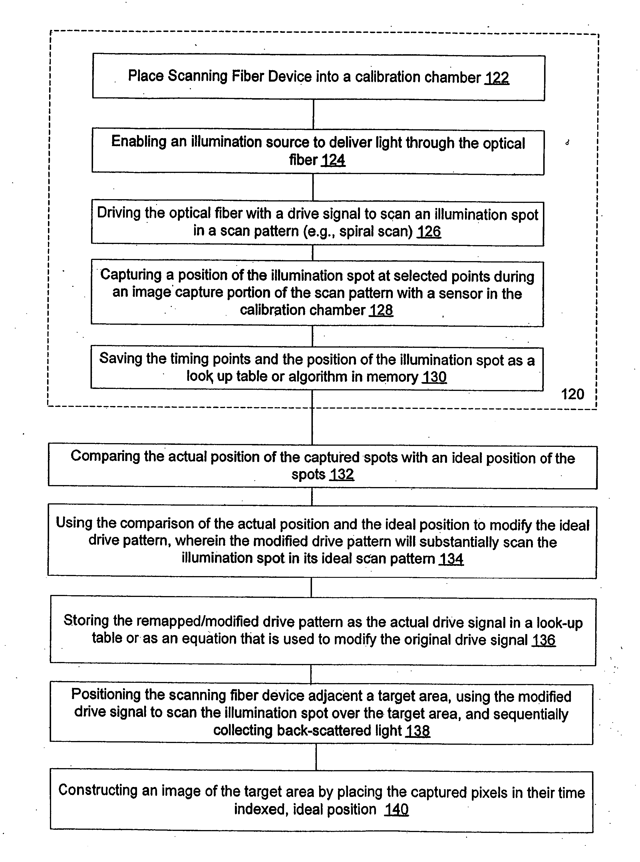
[0030] The present invention provides methods and systems that calibrate and characterize a scan pattern of a scanning beam systems and remap an image and / or remap a drive signal to reduce distortions that may be introduced into an image constructed by the scanning beam system.

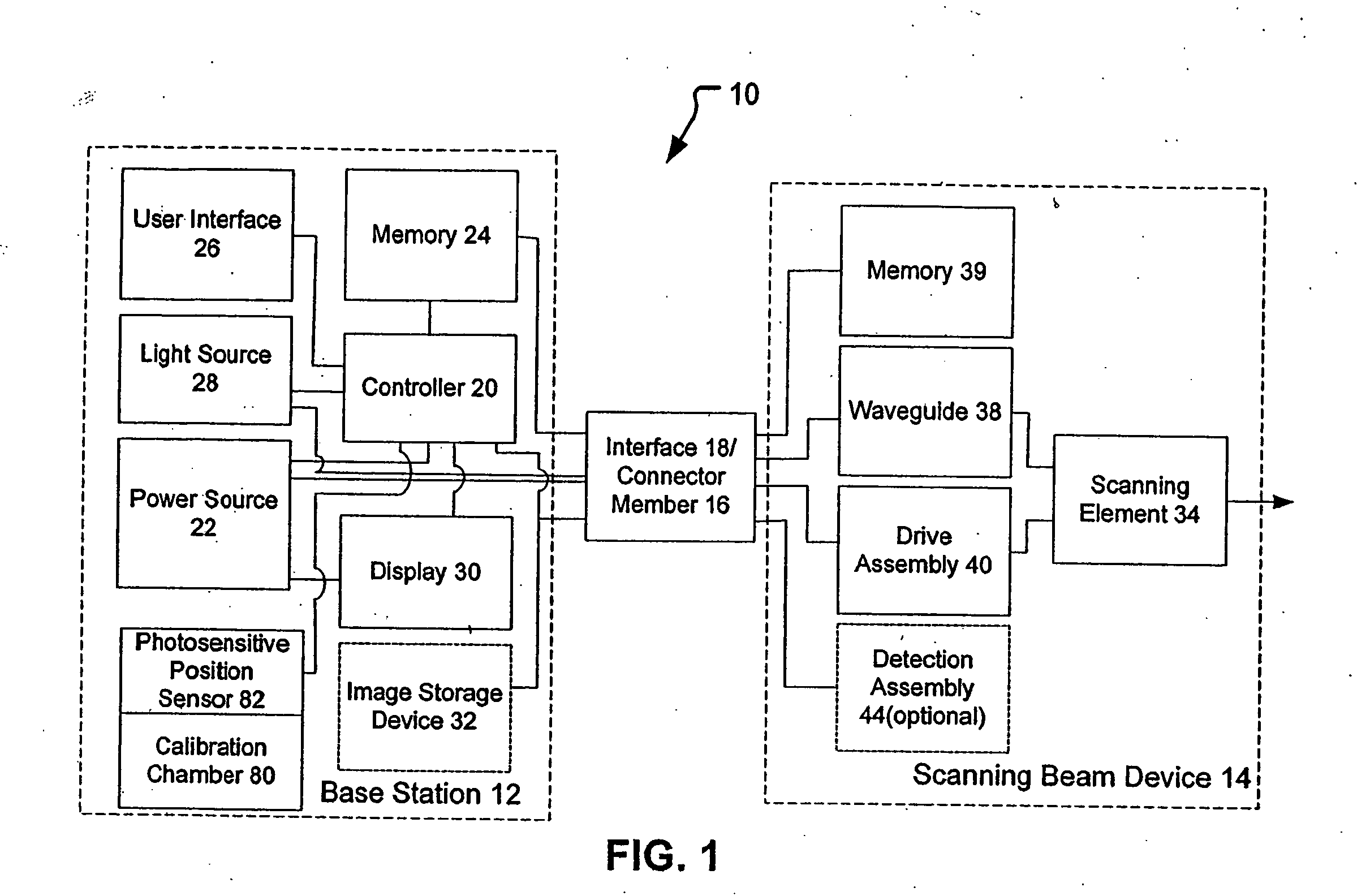
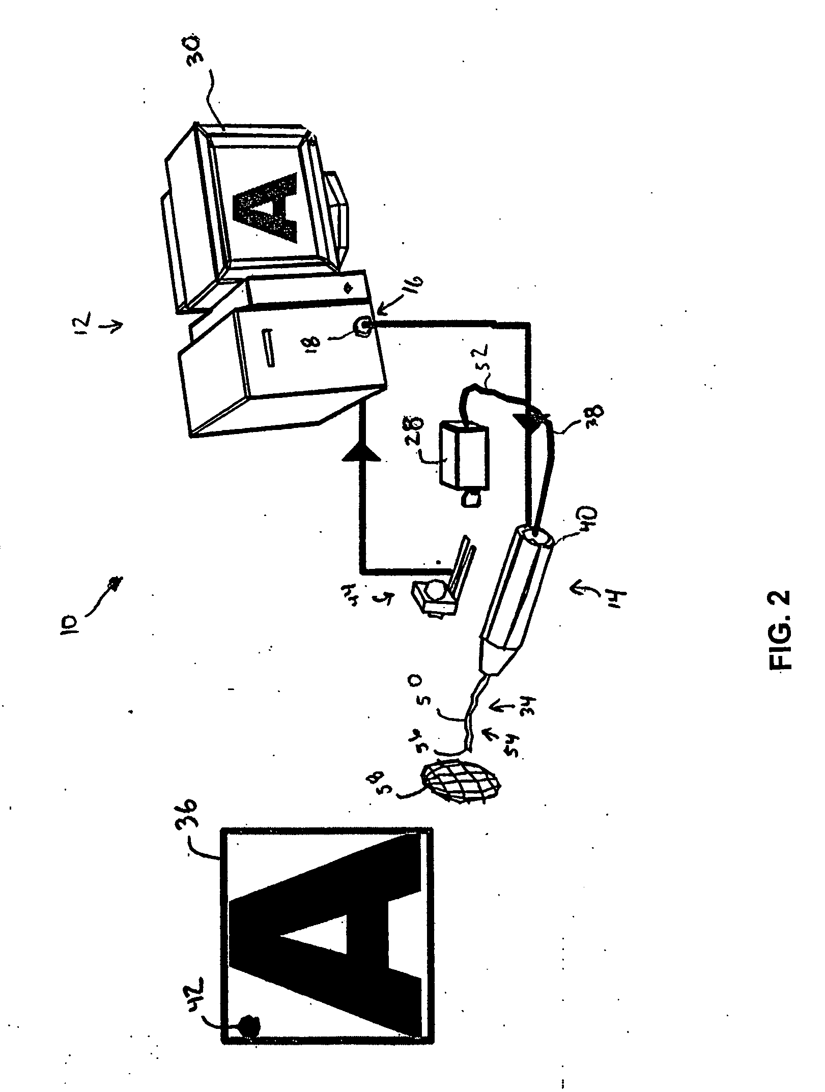
[0031] The scanning beam systems of the present invention will include a scanning beam device and a base station for controlling the scanning beam device. The scanning beam devices of the present invention may take on a variety of forms, but are typically in the form of an endoscope, catheter, fiberscope, microscope, boroscope, bar code reader, an image display, or other devices for generating images or acquiring images of a target area. The scanning beam devices of the present invention may be a limited use device (e.g., disposable device) or a multiple-use device. If the device is for medical use, the scanning beam devices will generally be sterile, either being sterilizable or being provided in hermeticall...


PUM


Abstract

The present invention provides software, methods, and systems for characterizing an actual scan pattern of a scanning beam device. The characterization of the actual scan pattern may be used in an image remapping method and / or a drive signal remapping method to reduce distortions in an image.

Description

BACKGROUND OF THE INVENTION [0001] The present invention relates generally to calibration and remapping methods for reducing the distortions in an image obtained by a scanning beam device. More specifically, the present invention relates to image remapping and drive remapping methods that reduce distortions caused by positional uncertainties of a scanning element during a scan pattern. [0002] One promising type of scanning beam device is a scanning fiber device. In a scanning fiber device, light is projected out of an end of a single, cantilevered optical fiber. The optical fiber is vibrated and scanned in one or two dimensions in a scan pattern so as to scan an illumination spot through an optional lens system and over a target area. Theoretically, knowing the drive signal that creates the scan pattern of the illumination spot allows a controller to know the exact position of the illumination spot throughout the scan pattern. Consequently, that allows for construction of an image o...

Claims


Application Information

Patent Timeline
Patent Type & Authority Applications(United States)
IPC IPC(8): G06K9/40H04N1/04G06V30/144G06V10/10G06V10/147
CPCG06K9/209G06K9/30H04N1/107G06K9/20G06V30/144G06V10/10G06V10/147H04N25/60H04N23/56G02B23/24G02B26/103G02B26/105H04N7/18H04N17/002G06F3/002
Inventor JOHNSTON, RICHARD S.
Owner UNIV OF WASHINGTON
Why Eureka
Try Eureka