Electronic gas flow measurement and recording device

a recording device and gas flow technology, applied in the direction of liquid/fluent solid measurement, volume measurement apparatus/methods, volume/mass flow by differential pressure, etc., can solve the problems of power requirements for read-only memory (rom) storage of data and retrieval of data therefrom, and achieve the effect of convenient retrieval and viewing

Inactive Publication Date: 2006-04-06
FLOWSTAR TECH
View PDF3 Cites 22 Cited by
  • Summary
  • Abstract
  • Description
  • Claims
  • Application Information

AI Technical Summary

Benefits of technology

[0017] The EFM of the present invention achieves these electrical power consumption reductions by greatly reducing the extent and complexity of the calculations required to be performed within the device itself. Continuous calculation of “real time” flow rates, in accordance with AGA-3, AGA-7, AGA-8, and / or NX-19 (as applicable), based on a steady flow of temperature and pressure input readings, requires a fast and powerful microprocessor, with correspondingly high electrical power requirements. However, the power requirements for storage of data in read-only memory (ROM), and for retrieval of data therefrom, are comparatively much lower. The EFM of the present invention substantially reduces the need for performing complex calculations in the computer itself, and instead uses ROM to store “look-up tables” containing data corresponding to parameters calculated in accordance with desired and selected standards (e.g., AGA standards) for selected ranges of input variables (e.g., gas temperature, pressure, chemical composition, and density). For applications using a turbine meter, data corresponding to the “K” factors for the turbine are also stored in ROM.

Problems solved by technology

However, the power requirements for storage of data in read-only memory (ROM), and for retrieval of data therefrom, are comparatively much lower.

Method used


Image

  • Electronic gas flow measurement and recording device
  • Electronic gas flow measurement and recording device
  • Electronic gas flow measurement and recording device

Examples


Embodiment Construction

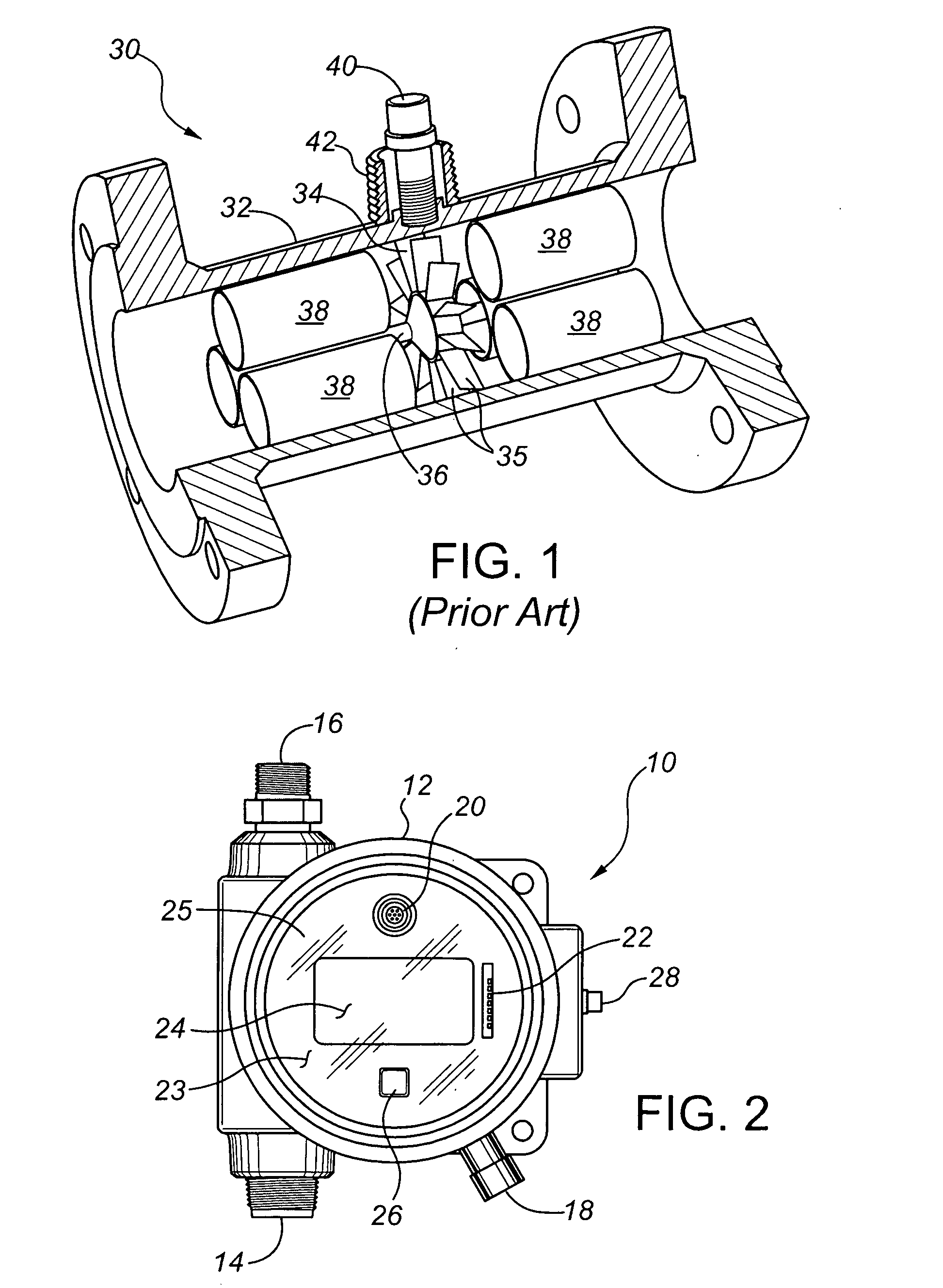
[0057]FIG. 1 illustrates a prior art turbine meter 30, mounted in a flanged pipe-spool housing 32 for connection into a pressurized gas line. The turbine meter 30 has a free-wheeling rotor 34 with multiple rotor blades 35. The rotor 34 is mounted on a shaft 36 that is substantially coaxial with the pipe spool. The turbine meter 30 may include flow straightening tubes 38 to promote non-turbulent flow through the meter 30, thus enhancing the accuracy of gas flow measurements made with the turbine meter 30. A sensing element 40 is housed in a riser 42 disposed in line with the rotor 34, for sensing and counting turbine rotations as previously described.

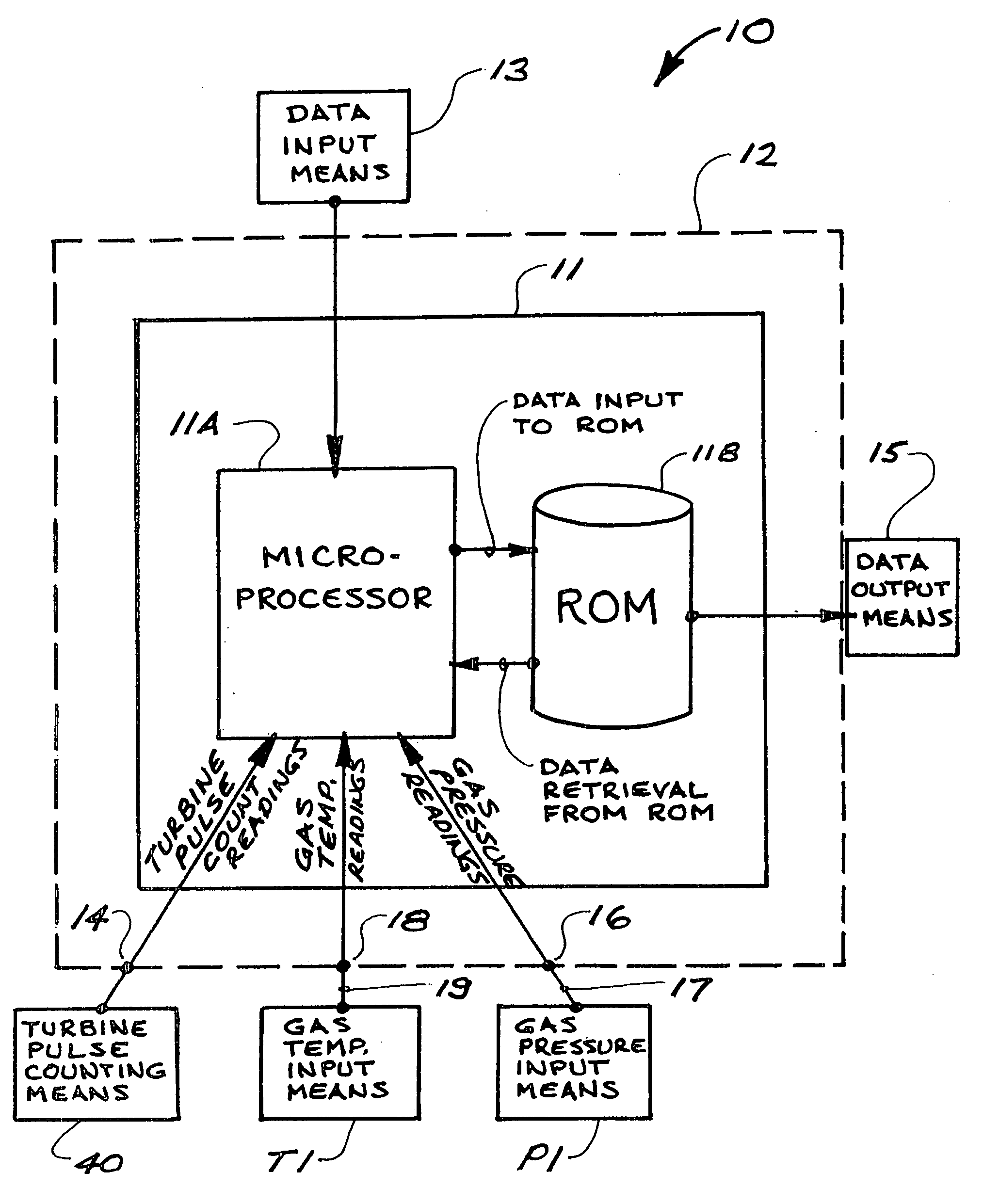
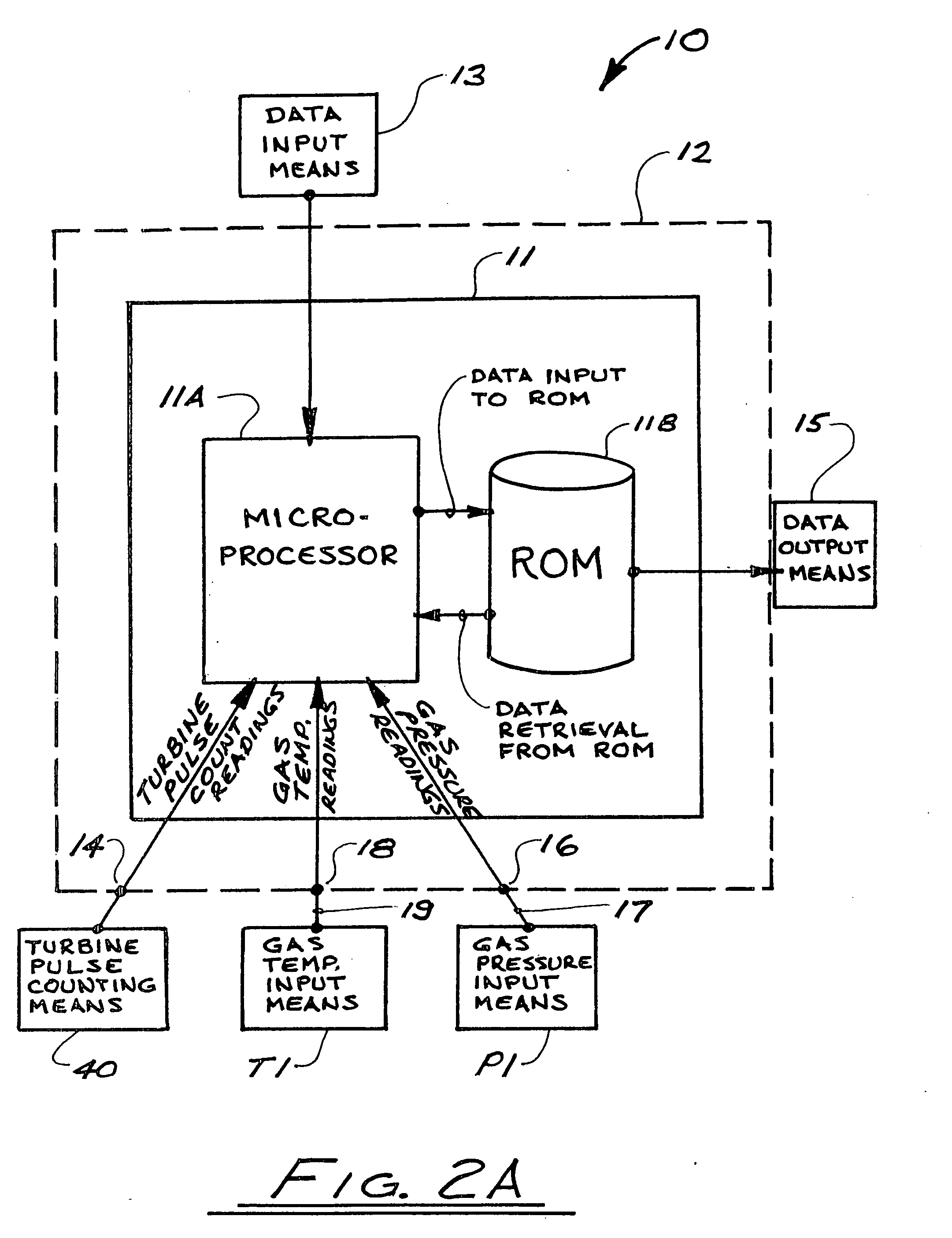
[0058]FIG. 2 illustrates an electronic flow measurement and recording device (“EFM”) 10 in accordance with the present invention, for use with a turbine flow meter. FIG. 2A is a block diagram of the EFM 10 and components thereof as will be described herein. The EFM 10 has a housing 12 which in the preferred embodiment will be an explosi...


PUM


Abstract

An electronic flow measurement device (EFM), for use in conjunction with a flow meter in a pressurized gas line, has a microprocessor and read-only memory (ROM), and calculates and records gas flow rates corrected for variable factors such as gas pressure, temperature, and density. Look-up tables stored in the ROM contain intermediate values calculated in accordance with selected protocols for selected ranges of input variables such as gas temperature, pressure, density, and turbine “K” factors. Based on inputs received from gas temperature and pressure sensors, the EFM selects corresponding intermediate values from the look-up tables, and then uses these values to calculate corrected gas flow rates, using software residing in the EFM. The microprocessor's power consumption is significantly reduced because the use of look-up tables reduces the complexity and extent of calculations that the EFM needs to perform, as compared with performing all required calculations in the EFM.

Description

CROSS-REFERENCE TO RELATED APPLICATIONS [0001] This application is a division of Application No. 10 / 790,194 filed Mar. 2, 2004, and the disclosure of said Application No. 10 / 790,194 is fully incorporated herein by reference.FIELD OF THE INVENTION [0002] The present invention relates to devices for measuring and recording the volumetric flow of pressurized gas in pipelines, particularly natural gas. BACKGROUND OF THE INVENTION [0003] Accurate measurement of gas flow in pipelines is important in a variety of situations, such as in the transmission of fuel gases such as natural gas and propane. Fuel gases are typically sold by volumetric measure, so gas flow must be accurately measured and recorded to ensure that customers are charged fully and fairly for the gas delivered to them. Accurate flow measurement is also important for optimum operational control in gas production and processing facilities. [0004] Gas flow measurement and recording are commonly carried out by use of an orific...

Claims


Application Information

Patent Timeline
Patent Type & Authority Applications(United States)
IPC IPC(8): G01F17/00
CPCG01F1/125G01F1/363G01F1/50G01F15/046G01F15/068
Inventor BELKE, BRADMACARTHUR, THOMASHURFORD, JACK
Owner FLOWSTAR TECH
Why Eureka
Try Eureka