[0014] Sheathing a core of blood with the miscible fluid, or assuring that the miscible fluid lies between at least a substantial portion of the blood and the enclosing boundaries of the flow path, prevents or at least limits contact of the blood with these boundaries. In turn, this configuration of the two fluids prevents or at least reduces the undesirable activation of factors in the blood, thereby minimizing bioincompatibilities that have been problematic in prior techniques of blood processing.
[0015] The invention also eliminates or at least substantially reduces the
fouling reactions that have been known to be a major deterrent to the
continuous use of an
extracorporeal extraction device. In particular, as the primary transport surface in the membraneless exchange device (also referred to herein as a membraneless separator) of the invention is intrinsically non-
fouling, a major deterrent to long-term or
continuous operation is removed, opening the possibility to the design and construction of small, wearable devices or systems with the recognized benefits of nearly continuous blood treatment. Such a device or
system could be very small and worn or carried by the patient (e.g., outside of a hospital or clinic setting), and could be supplied with external buffer reservoirs (in a back-pack, briefcase, or from a reservoir located in the home, located at the place of work, etc.). Further, because fouling would be reduced, and sustained operation at low blood flows over long times would be allowed, such anticoagulation as might be required is likely to have an effect confined to the
extracorporeal circuit. As understood by those skilled in the art, avoiding systemic anticoagulation outside of the clinic is highly desirable.
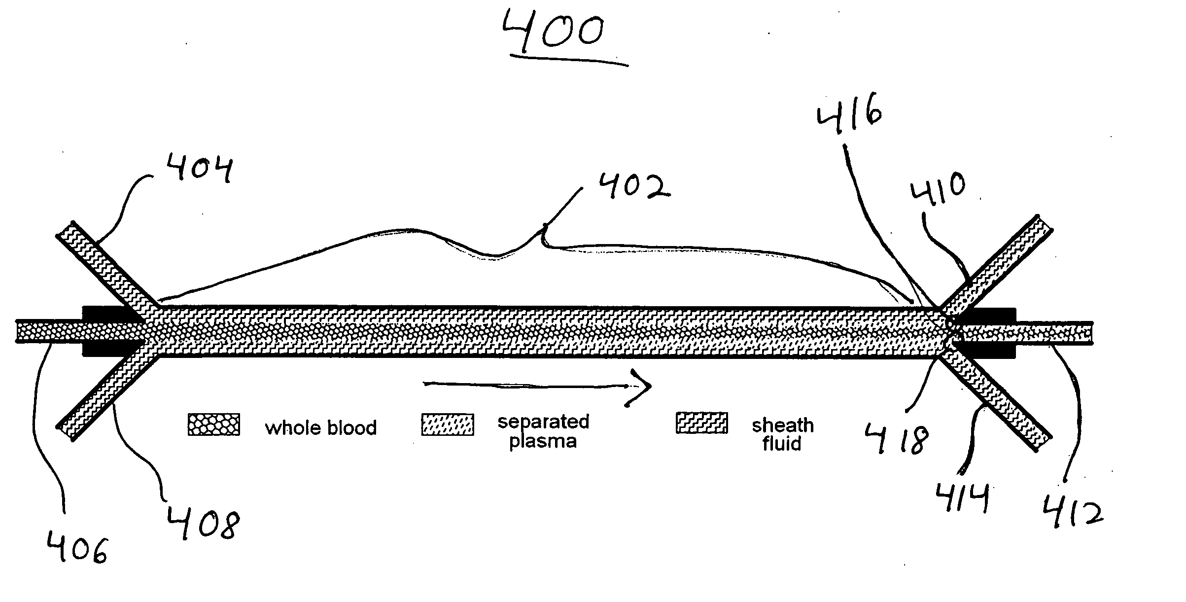
[0016] The devices, systems and methods of the invention described herein also have the benefit of being capable of diffusing various blood components having different sizes. In particular, the flow of blood and a miscible fluid with which it is in contact can be controlled for the purpose of achieving the desired separation of components. For example, flow adjustment can minimize cellular migration across the interface. A sheath fluid can be used to give the discrimination of a membrane between large and small molecules that cannot be achieved by a denuded interface, no matter how
exposure time (adjacent flows) is varied. For example, as explained below, various flow conditions may be used that cause blood cells to move away from the blood-
liquid interface, thereby making it is possible to “skim” blood in order to remove substantial amounts of
plasma, without cells.
[0017] As also discussed below, membraneless contact of a
thin layer of blood with a sheathing fluid according to the present invention may be used to cause high rates of exchange per unit area of blood-sheathing fluid contact for all solutes, but with a discrimination among free (unbound) solutes that is less than the square-root of the ratio of their
diffusion coefficients. Moreover, while high exchange rates (e.g., of toxic substances) are often desirable, indiscriminate transport is not. Therefore, according to the principles of the present invention, a membraneless exchange device as described herein is used in conjunction with at least one secondary processor (e.g., a membrane device or other type of separator) in order to
restrict the removal of desirable substances and effect the removal of undesirable substances from blood. The efficiency of such a secondary separator is greatly increased by the use of a primary separator that is capable of delivering
cell-depleted (or
cell-free) fractions of blood to it. Therefore, according to another aspect of this invention, transport of molecular components of blood to the sheathing fluid may be indiscriminate. The sheathing fluid, carrying both molecular components which are, and those which are not, desirable to remove from blood, is provided to the secondary separator, such that the fluid entering the secondary separator is substantially
cell-free. The secondary separator, meanwhile, regulates the operation of the membraneless separator through the composition of the recycle
stream that it returns (directly or indirectly) to the sheath fluid inlets of the membraneless separator. According to the principles of the present invention, moreover, a membrane-based secondary separator used in this manner is able to achieve much higher separation rates because
concentration polarization (i.e., the accumulation of material rejected by the secondary separator on the upstream side of the separator) is limited to proteins and does not involve cells. Moreover, because cells would be retained in the primary separator (i.e., the membraneless exchange device), they would see artificial material only on its conduit surfaces, not on its liquid-liquid contact area, whence bioincompatibilities should be much reduced. As such, it should be understood that the need for anticoagulation may be greatly reduced or eliminated.

