Synchronization signal detection in a digital television receiver

a technology of synchronization signal and digital television receiver, which is applied in the direction of differential synchronisation source locking, selective content distribution, television system, etc., can solve the problems of affecting the ability of the receiver, unable to determine the main path properly using and unable to determine the main path properly by the receiver of the related ar

Active Publication Date: 2006-04-13
SAMSUNG ELECTRONICS CO LTD
View PDF0 Cites 39 Cited by
  • Summary
  • Abstract
  • Description
  • Claims
  • Application Information

AI Technical Summary

Problems solved by technology

The primary challenge that faces designers in designing receivers so that they achieve good reception is the presence of multipath interference due to multiple signal paths in the channel.
Such multipath interference affects the ability of the receiver to recover signal components such as the carrier and symbol clock.
In a multipath environment, it is important to find quickly main path but sometimes it is impossible to determine properly the main path using receivers of the related art.
But if only the real part signal is used in the synchronization, sometimes it may be impossible for the receivers of the related art to determine properly the main path (B).
If there is phase offset, the correlation value of the real part of the main path signal is so small that it may be difficult of impossible to synchronize.

Method used


Image

  • Synchronization signal detection in a digital television receiver
  • Synchronization signal detection in a digital television receiver
  • Synchronization signal detection in a digital television receiver

Examples


Embodiment Construction

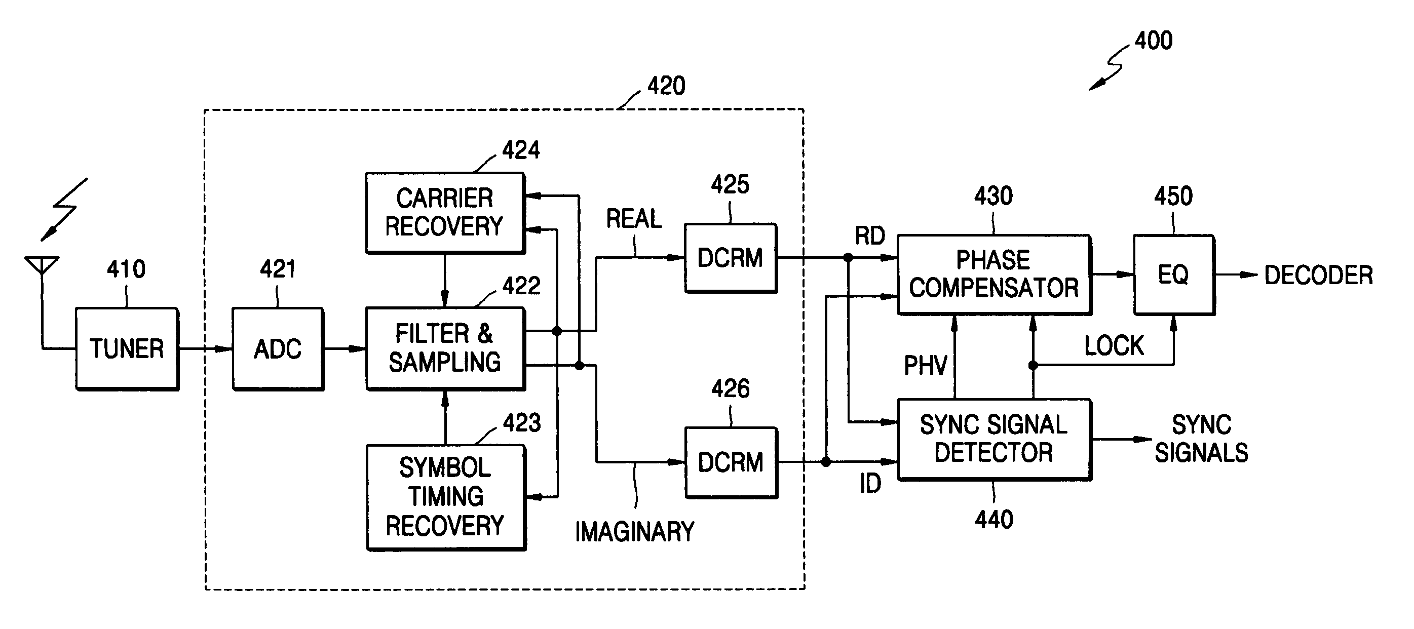
[0052]FIG. 7 is a circuit block diagram illustrating a digital television (DTV) receiver comprising a Sync Signal Detector 440 and a Phase Compensator 430 according to an embodiment of the present invention. The DTV receiver comprises related art components including a antenna connected to a tuner (410), a Demodulator circuit 420, and an Equalizer (EQ 450).

[0053] The Tuner (410) receives the 6 MHz signal (UHF or VHF) from an external antenna (shown). The Demodulator circuit 420 includes an Analog-to-Digital Converter (ADC 421), a Carrier Recovery circuit (424), a Filtering and Sampling circuit (422) a Symbol Timing Recovery circuit (423), a Real-signal circuit (DCRM 425) and an Imaginary-signal circuit (DCRM 426).

[0054] Carrier recovery (424) in the DTV system is performed using the low-level, inband pilot that is added to the random data signal by the transmitter (not shown). The presence of a low-level pilot allows the DTV (VSB) receiver to frequency-lock to the incoming signal ...


PUM


Abstract

A digital television (DTV) receiver is provided, comprising: a demodulator that demodulates television signals and outputs equalizer training signals in the form of real (I) and imaginary (Q) data; a sync signal detector, and a phase compensator that offsets the phase of the I and Q data based on the phase offset signal and outputs phase adjusted I data under control of the lock control signal. The sync signal detector comprises: a correlator that correlates the equalizer training signals including the I and Q data; a power calculator that calculates the sum of the power of the correlated I and Q data; a comparator that compares (the sum) against a preset threshold and outputs a compare indication signal; a sync lock controller that monitors the compare indication signal and outputs a lock control signal; and a phase calculator that calculates a phase of the equalizer training signals based on the I and Q data and outputs a phase offset signal based on the compare indication signal.

Description

BACKGROUND OF THE INVENTION [0001] 1. Field of the Invention [0002] The present invention relates to digital television (DTV) receivers, and more particularly to reliable synchronization detection circuits for use therein. [0003] 2. Description of the Related Art [0004] Advances in technology now allow for the transmission of digital television (DTV) in the same bandwidth currently used by NTSC (analog) television transmissions. Digital transmission offers improved video and audio reception. The DTV standard for the United States was adopted on Dec. 24, 1996, and allows digital transmission of high quality video and audio signals, in particular high definition television (HDTV). Since the adoption of the digital television (DTV) standard, there has been an ongoing effort to improve the design of DTV receivers. [0005] The primary challenge that faces designers in designing receivers so that they achieve good reception is the presence of multipath interference due to multiple signal p...

Claims


Application Information

Patent Timeline
Patent Type & Authority Applications(United States)
IPC IPC(8): H04N5/21
CPCH04L25/03019H04L27/06H04L2025/0377H04L2027/0032H04L2027/0067H04L2027/0089H04L2027/0095H04N5/4401H04N5/455H04N21/2383H04N21/4263H04N21/4382H04N21/426H04N5/04
Inventor CHEON, JONGHWANKIM, MINHOJEON, HYUNBAEZHIDKOV, SERGEY
Owner SAMSUNG ELECTRONICS CO LTD
Why Eureka
Try Eureka