Heave compensated snubbing system and method

Inactive Publication Date: 2006-04-13
CUDD PRESSURE CONTROL
View PDF6 Cites 12 Cited by
  • Summary
  • Abstract
  • Description
  • Claims
  • Application Information

AI Technical Summary

Benefits of technology

[0005] In the prior art snubbing operations it is difficult to transfer tubulars from the platforms pipe handling system to the snubbing jack due to the heave of the platform. Often the heaving significantly reduces the time windows available to perform snubbing operations.
[0007] The floating platform may be, but is not limited to, a drilling vessel or a semi-submersible rig. The platform preferably includes pipe handling equipment and systems. The present invention facilitates the transfer of tubulars between the platform and the snubbing jack and allows the makeup and breakout of the tubulars with the platforms pipe handling equipment while the tubulars and held by the snubbing jack.
[0011] The heave compensation system of the present invention may further include supporting the snubbing jack by a riser tensioning system. This configuration facilitates operating the system without traditional support frames utilized in prior snubbing systems.

Problems solved by technology

In the prior art snubbing operations it is difficult to transfer tubulars from the platforms pipe handling system to the snubbing jack due to the heave of the platform.
Often the heaving significantly reduces the time windows available to perform snubbing operations.

Method used


Image

  • Heave compensated snubbing system and method
  • Heave compensated snubbing system and method
  • Heave compensated snubbing system and method

Examples


Embodiment Construction

[0018] Refer now to the drawings wherein depicted elements are not necessarily shown to scale and wherein like or similar elements are designated by the same reference numeral through the several views.

[0019] As used herein, the terms “up” and “down”; “upper” and “lower”; and other like terms indicating relative positions to a given point or element are utilized to more clearly describe some elements of the embodiments of the invention. Commonly, these terms relate to a reference point as the surface from which drilling operations are initiated as being the top point and the total depth of the well being the lowest point.

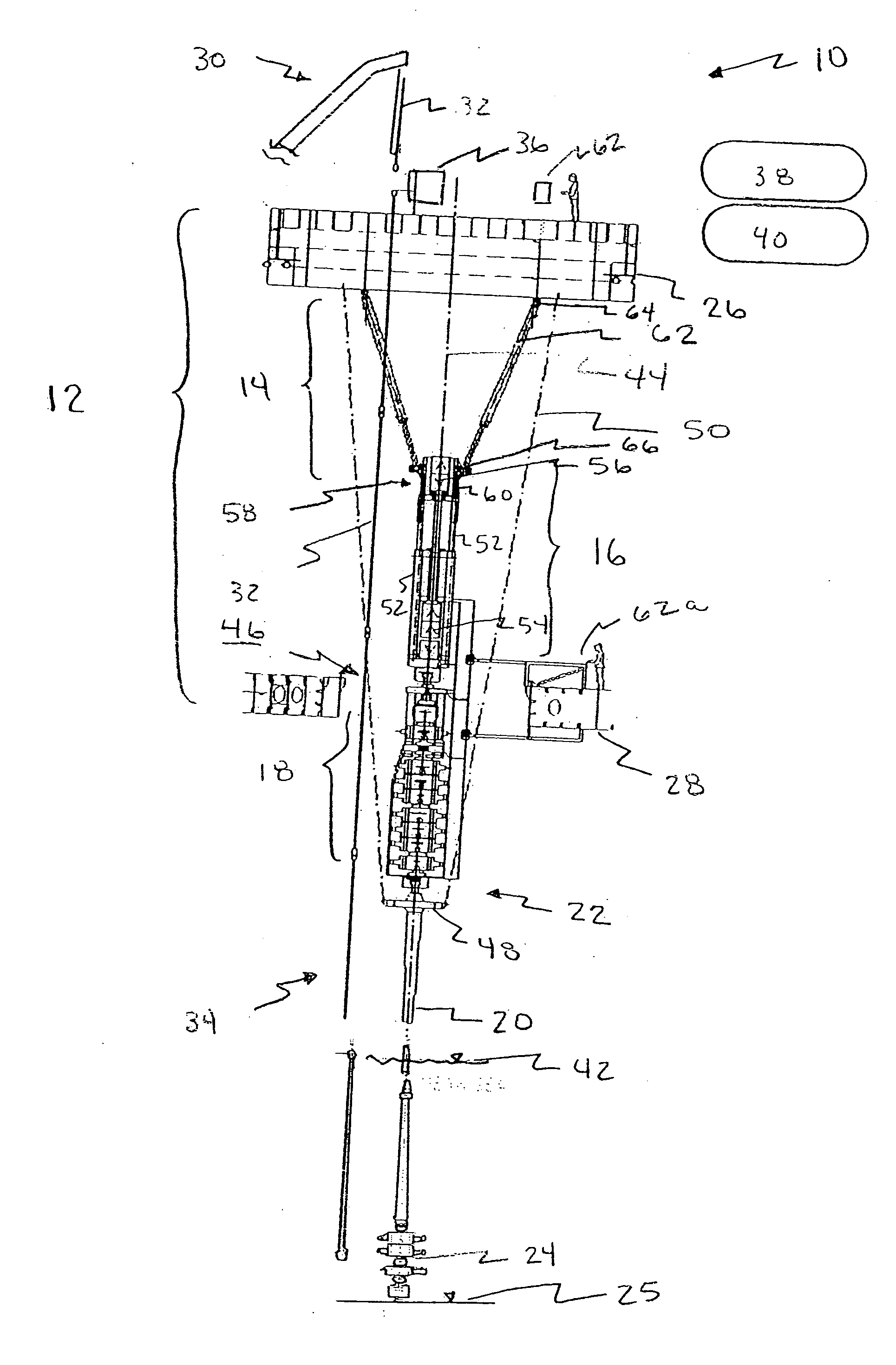
[0020]FIG. 1 is a perspective view of an embodiment of a heave compensated snubbing system, generally referred to by the numeral 10, of the present invention. System 10 includes a floating platform 12, a compensation system 14, a snubbing jack 16, a blowout preventer (BOP) stack 18, a riser 20, a riser tensioning system 22, and a wellhead 24.

[0021] Floating platf...


PUM


Abstract

A heave compensation system to enable the transfer of tubulars between a floating platform and a snubbing jack. The heave compensation system includes a first end connected to the floating platform and a second end in connection with a traveling slip assembly of the snubbing jack, the heave compensation system is operable between a disengaged position and an engaged position. When the heave compensation system is in the disengaged position the traveling slip assembly moves separate and independent from the movement of the floating platform, and when the heave compensation system is in the engaged position the traveling slip assembly is locked in a constant position relative to the floating platform.

Description

RELATED APPLICATIONS [0001] This application claims the benefit of U.S. Provisional Patent Application No. 60 / 584,899 filed Jul. 1, 2004, incorporated in its entirety herein by reference.FIELD OF THE INVENTION [0002] The present invention relates in general to drilling operations and more specifically to subsea wellbore operations performed from a floating platform. BACKGROUND [0003] Wells are often drilled in water environments wherein the well is accessed from a floating platform such as a drilling ship or a floating rig such as semi-submersible rigs. Theses floating platforms move up and down as a result of wave motion. The heaving of the floating platform makes it difficult to conduct wellbore operations and often requires that the operations cease. It is especially difficult to transfer pipe to and from snubbing units for conducting snubbing operations when the platform heaves. [0004] Therefore, it is a desire to provide a heave compensation system that facilitates transfer of ...

Claims


Application Information

Patent Timeline
IPC IPC(8): E02D15/02E02D5/54
CPCE02D27/52E21B19/002
Inventor OLSEN, BERNTLAGENDYK, RANDALL D.BALLARD, BERTRAM JR.VAUGHAN, GARYBICKLE, HIRAM L.RUDSHAUG, BJORN
Owner CUDD PRESSURE CONTROL
Why Eureka
Try Eureka