System and method for reticle protection and transport

a technology of reticles and transport devices, applied in the field of lithography, can solve the problems of large clean room size, prone to contamination, and high cost of maintaining a clean room, and achieve the effect of reducing the potential for reticle contamination

Inactive Publication Date: 2006-04-13
ASML HLDG NV
View PDF11 Cites 14 Cited by
  • Summary
  • Abstract
  • Description
  • Claims
  • Application Information

AI Technical Summary

Problems solved by technology

A considerable amount of expense is associated with maintaining a clean room.
This expense is related, in part, to the size of the clean room and the equipment needed to maintain it.
For example, as reticles are transported from one stage in a lithographic process to another, they are susceptible to contamination due to particles found within the processing area.
In some cases, clean rooms are oxygen deficient and therefore unfit for human occupancy.
Vibration, pressure shock, and turbulent air flow can result from opening the box and may stir up particles that are initially resting on the internal surfaces of the box, such as the top-side of the base or the inner walls and ceiling of the lid.
However, the use of the reticle fastener presents an opportunity for contamination from the contact between the reticle and the reticle fastener.
This is a new problem in the context of lithography tools, since the EUV tool is the first tool to expose the reticle in vacuum and without a protective pellicle.
A similar problem has been encountered before by those who design the tools that write masks, henceforth “mask writer tools”.
The Yoshitake solution, however, introduces additional problems to be solved.
Consequently, there is a potential for contamination of the masks when the closed box or pod is opened.
This creates the potential for cross-contamination.

Method used


Image

  • System and method for reticle protection and transport
  • System and method for reticle protection and transport
  • System and method for reticle protection and transport

Examples


Embodiment Construction

[0029] Embodiments of the present invention will now be discussed in detail. While specific features, configurations and arrangements are discussed, it should be understood that this is done for illustration purposes only. A person skilled in the relevant art will recognize that other steps, configurations and arrangements or devices may be used to achieve the features of the invention without departing from the spirit and scope thereof. Indeed, for the sake of brevity, conventional electronics, manufacturing of semiconductor devices, and other functional aspects of the method / apparatus (and components of the individual operating components of the apparatus) may not be described in detail herein.

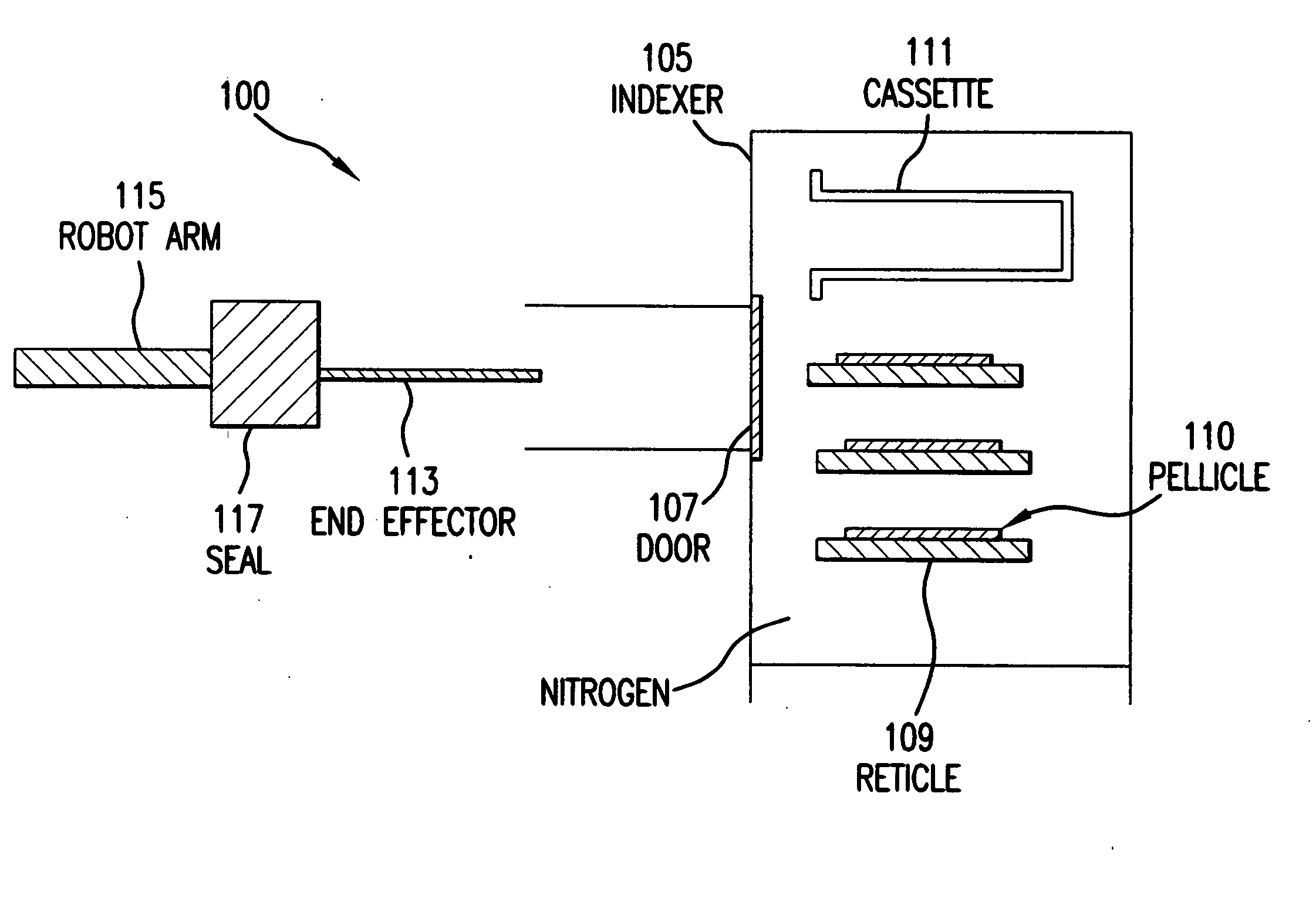
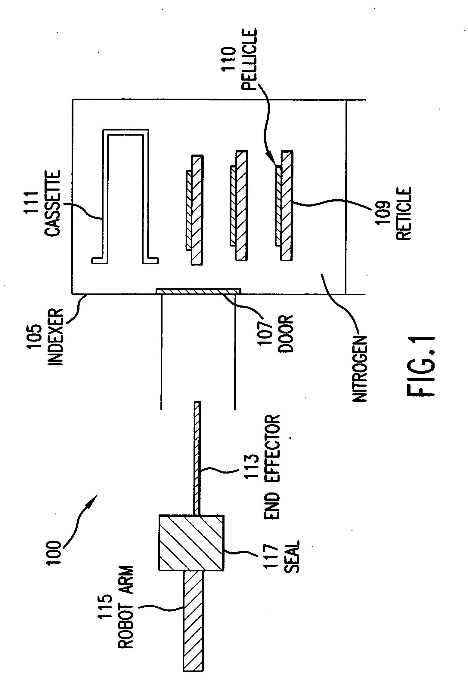
[0030]FIG. 1 illustrates a reticle transport system 100 for a lithography tool. The reticle transport system 100 includes an indexer 105. In accordance with an embodiment of the present invention, the indexer 105 further comprises a library of shelves (not shown) within the lithography tool...


PUM

PropertyMeasurementUnit
atmospheric pressureaaaaaaaaaa
permeableaaaaaaaaaa
impermeableaaaaaaaaaa

Abstract

A substrate protection and transport system and method for transitioning a substrate from atmospheric pressure to vacuum in a lithography tool. The system includes one or more removable substrate transport cassettes that support a substrate. The cassette can include a base portion and top portion, and can include a seal. Each cassette has at least one vent and at least one filter. The system further includes a box having a base and lid. The box holds one or more cassette-substrate arrangements. A storage rack having shelves for holding the box-cassette-substrate arrangement is also provided. Further, an entry-exit module having a loadlock is provided for transitioning the cassette-substrate arrangement from atmospheric pressure to vacuum. The entry-exit module can include a shuttle and / or elevator for transporting the cassette-substrate arrangement. During transitioning, the filter(s) and vent(s) restrict particles within the loadlock from entering the cassette-substrate arrangement and reaching a surface of the substrate.

Description

CROSS-REFERENCE TO RELATED APPLICATIONS [0001] This application is a divisional of U.S. patent application Ser. No. 10 / 216,660, filed Aug. 12, 2002 (now pending), which is a continuation-in-part of U.S. patent application Ser. No. 09 / 925,722, filed Aug. 10, 2001 (now U.S. Pat. No. 6,619,903 B2, issued Sep. 16, 2003), both of which are incorporated herein by reference in their entireties.BACKGROUND OF THE INVENTION [0002] 1. Field of the Invention [0003] This invention relates generally to lithography, and more specifically to the protection of lithographic reticles. [0004] 2. Related Art [0005] Lithography is a process used to create features on the surface of targets. Such targets can include substrates used in the manufacture of flat panel displays, circuit boards, various integrated circuits, and the like. A semiconductor wafer, for example, can be used as a substrate to fabricate an integrated circuit. [0006] During lithography, a reticle, which is another exemplary substrate, i...

Claims


Application Information

Patent Timeline
Patent Type & Authority Applications(United States)
IPC IPC(8): H01L21/677G03F1/24G03F1/66G03F7/20H01L21/027H01L21/673
CPCB82Y10/00B82Y40/00G03F1/24G03F1/66G03F7/70741G03F7/70808H01L21/67005H01L21/67751H01L21/67772H01L21/67778Y10S414/14H01L21/68
Inventor DEL PUERTO, SANTIAGO E.DEMARCO, MICHAEL A.FRIEDMAN, GLENN M.IVALDI, JORGE S.MCCLAY, JAMES A.
Owner ASML HLDG NV
Why Eureka
Try Eureka