Surgical tube guard

a tube guard and tube technology, applied in the field of surgical tubes, can solve the problems of unsatisfactory action, patient bite, obvious danger to the patient, etc., and achieve the effect of convenient installation and removal

Inactive Publication Date: 2006-04-20
CYMPLE MEDICAL PROD
View PDF20 Cites 46 Cited by
  • Summary
  • Abstract
  • Description
  • Claims
  • Application Information

AI Technical Summary

Benefits of technology

[0013] The aforementioned needs are satisfied by the LMA bite-block apparatus of the present invention which, in one aspect, comprises a bite structure that is dimensioned so as to be interposed between the patient's molars on one side of the mouth to inhibit the patient from closing their mouth. In this aspect, the apparatus further includes a capture opening that is sized so as to receive an LMA air tube. In one particular implementation, the capture opening is open on one side so as to facilitate installation and removal of the LMA air tube from the capture opening.

Problems solved by technology

During the use of the LMA, however, patients often bite down on the LMA tube.
This action is undesirable for several reasons.
The first reason is the obvious danger to the patient due to blockage of the breathing airway passage.
The second is that biting the LMA tube can result in damage to the tube which can puncture or sever the tube, thereby compromising the ability of the tube to deliver oxygen to the patient.
This design presents a number of practical problems during use.
This will result in high forces exerted over a small area, giving rise to large pressures on the bite block when the patient bites down on it, which can lead to failure of the block.
Further, a three-sided bite block structure is mechanically weaker than a structure which fully surrounds the air tube.
For these reasons, extra material or stronger plastics are required to raise the bite-block strength, increasing the cost of the device.
Moreover, the large size of the air tube bite-block and its position obstruct the oral cavity.
This obstruction complicates the use of other devices, such as suction devices which are commonly inserted into the mouth during oral procedures.
Additionally, positioning the bite block in the center of the mouth makes it more difficult for the physician to see into the oral cavity.
Yet a further difficulty is that these bite blocks use elongated U-shaped channels to hold the LMA tube over relatively long lengths.
Consequently, this installation can be difficult and time consuming for the treating medical personnel.
Similarly, removal of the air tube from the bite block can also be more complicated.
These designs are still complicated to use and often result in greater obstruction in the patient's mouth.

Method used


Image

  • Surgical tube guard
  • Surgical tube guard
  • Surgical tube guard

Examples


Embodiment Construction

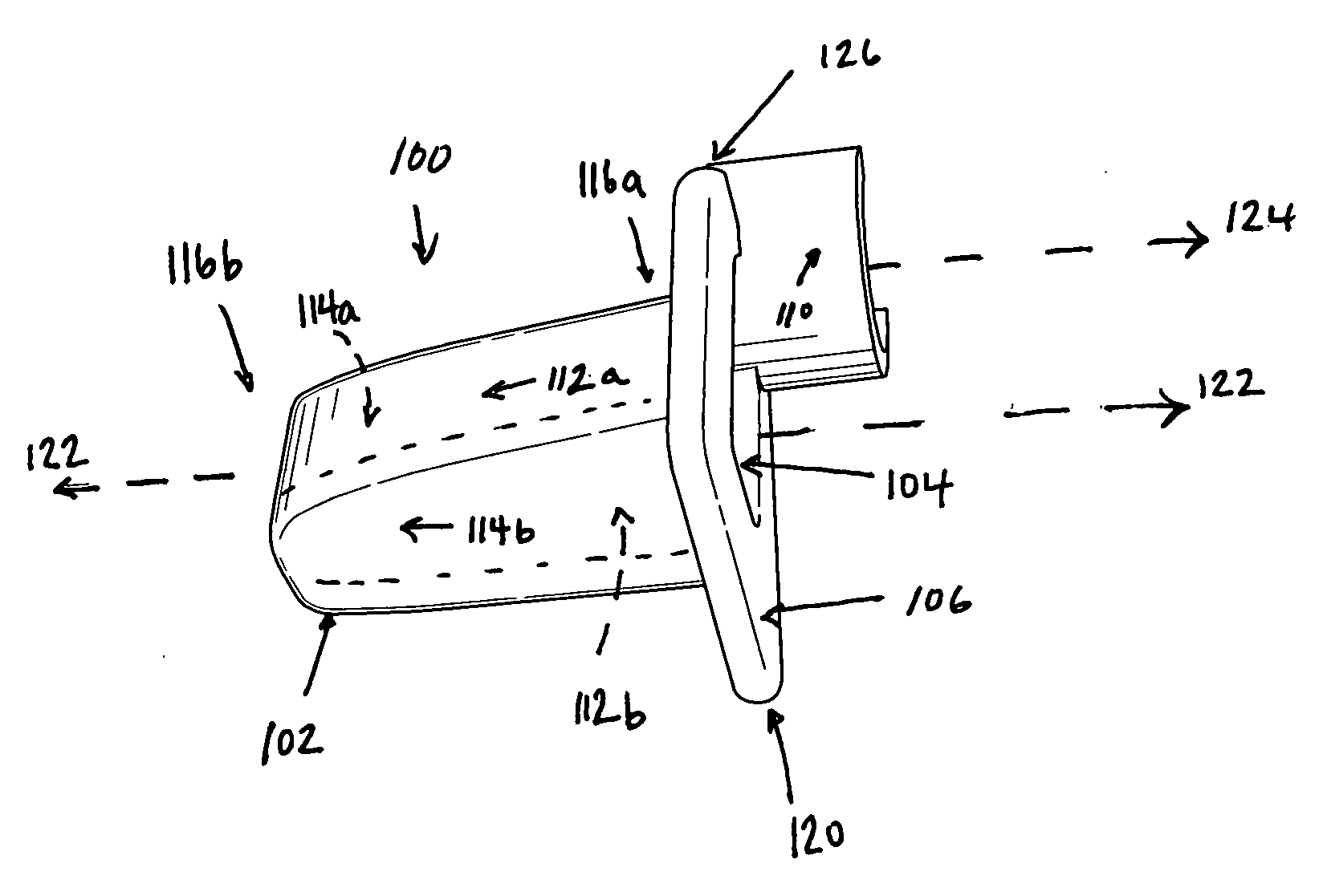
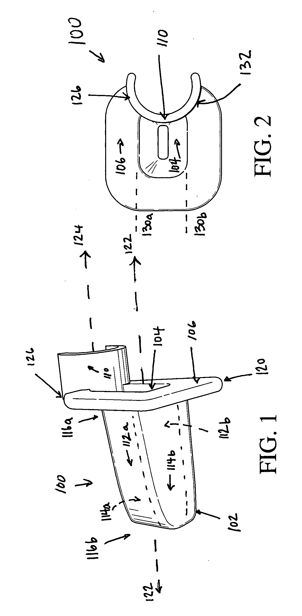
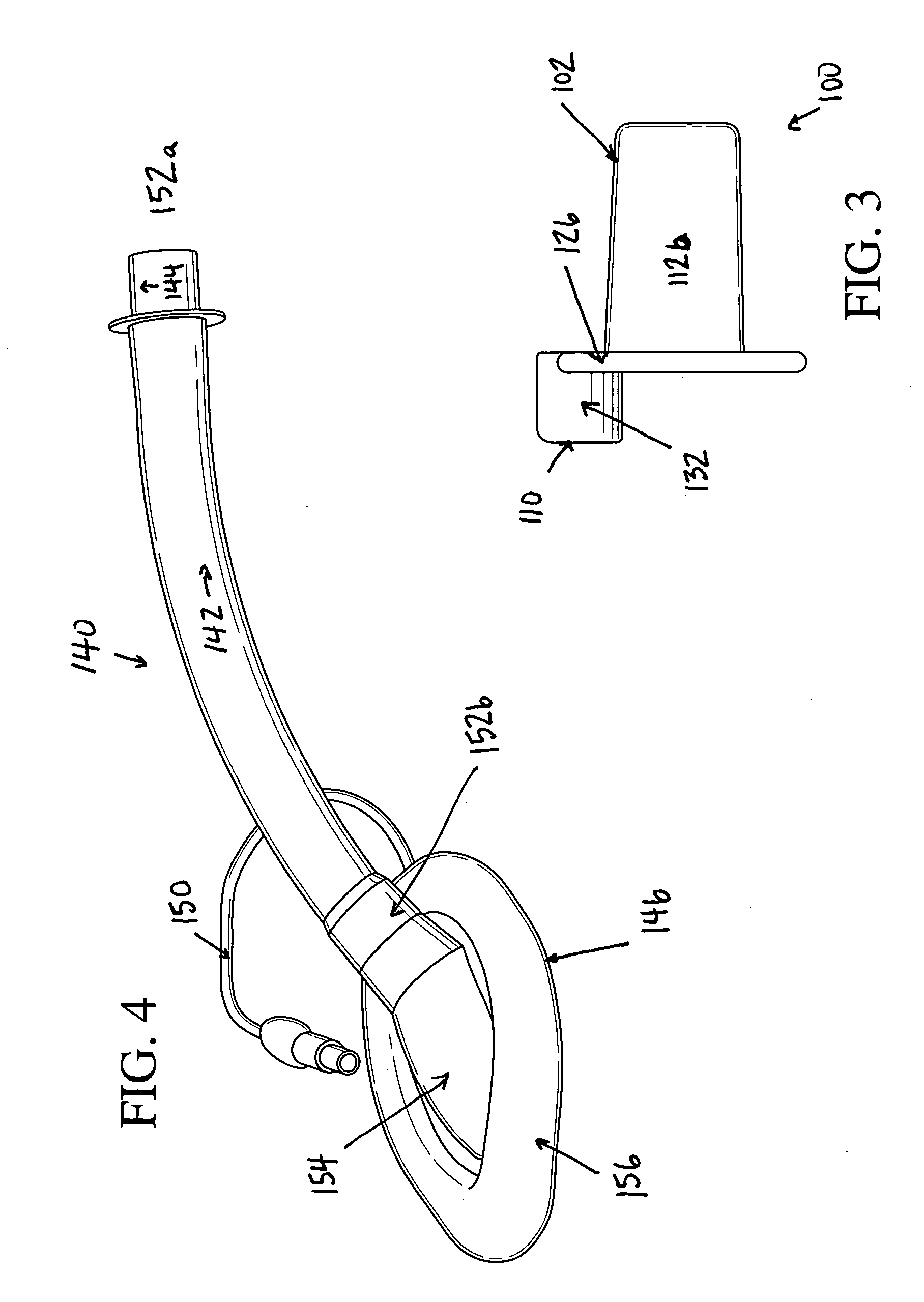
[0025]FIG. 1 illustrates one embodiment of a perspective view of an LMA bite-block device 100. Generally, the device 100 is designed for partial placement within a patient's mouth so as to protect an inserted air tube, such as an LMA tube, from damage or occlusion resulting from the patient biting the tube. The device includes a bite-block body 102, a central cavity 104, a flange 106, and a tube coupling mechanism 110.

[0026] The bite-block 100 possesses a generally elongate bite-block body 102, comprising top and bottom walls 112a and 112b, side walls 114a and 114b, and a first end 116a and a second end 116b. The bite-block body 102 is preferably dimensioned such that, when inserted between the patient's molars, the patient's front teeth are separated by a distance that is greater than the width of the air tube. In the embodiment illustrated in FIG. 1, the top and bottom walls 112a and 112b are approximately ¾″ wide by 1¼″ long. The side walls extend a width, on average, of approxi...


PUM


Abstract

A bite-block device for preventing biting of air tubes, such as laryngeal mask airway (LMA) tubes by human teeth is disclosed. The device is composed of a generally cylindrical body, fabricated from a biologically compatible polymer. A hole is present through the long axis of the body. The device also extends in a plane perpendicular to the long axis of the body. Attached to this plane is a coupling device intended for securing an LMA tube to the bite-block. The bite-block is positioned within a patient's mouth against the cheek, with the plane perpendicular to the long axis pressed against the lip. Deployed in this fashion, the bite block engages the molars, bicuspids, and cuspids, preventing contact of the teeth with an LMA tube.

Description

CROSS-REFERENCE TO RELATED APPLICATIONS [0001] This application claims the benefit of U.S. provisional application No. 60 / 615,219 by Kion H. Gould entitled “Surgical Tube Guard,” filed on Oct. 1, 2004.BACKGROUND OF THE INVENTION [0002] 1. Field of the Invention [0003] The present invention relates to a surgical apparatus and, in particular, concerns a guard for protecting tubes which are inserted into a patient's mouth during surgery. [0004] 2. Description of the Related Art [0005] The laryngeal mask airway (LMA) is a medical device that has found widespread utility in anesthetic practice and emergency medicine. The device is used by surgeons and rescue personnel to ensure that a patient is able to breathe during medical procedures. The device consists of a wide tube with a connector at one end and an elliptical, inflatable mask at the opposite end. The mask is passed through the passage which extends from the mouth and nasal cavity (the pharynx) until resistance is felt. At this po...

Claims


Application Information

Patent Timeline
Patent Type & Authority Applications(United States)
IPC IPC(8): A61M16/00A62B9/06
CPCA61M16/0488A61M16/0493A61M16/0409A61B1/00154
Inventor GOULD, KION H.
Owner CYMPLE MEDICAL PROD
Why Eureka
Try Eureka