Mounting case for electro-optical device, electro-optical device and electronic apparatus

a technology of electro-optical devices and mounting cases, applied in non-linear optics, instruments, optics, etc., can solve the problems of severe bent flexible wiring boards, damaged flexible wiring boards, and damage to flexible wiring boards, so as to prevent the damage of flexible wiring boards, increase the cooling effect of electro-optical panels, and suppress the generation of hot spots

Active Publication Date: 2006-04-20
SEIKO EPSON CORP
View PDF2 Cites 11 Cited by
  • Summary
  • Abstract
  • Description
  • Claims
  • Application Information

AI Technical Summary

Benefits of technology

[0007] An advantage of the present invention is that it provides a mounting case for an electro-optical device, which can prevent a portion led from a flexible wiring board from being damaged, an electro-optical device having the mounting case, and an electronic apparatus having the electro-optical device.
[0008] According to a first aspect of the invention, a mounting case for an electro-optical device accommodates an electro-optical panel that is used in the electro-optical device in which display images are displayed, electrical signals are transmitted to and from the outside through the mounting case. The mounting case for an electro-optical device includes a body portion which is constructed to accommodate the electro-optical panel in a state in which one end of a flexible wiring board for transmitting the electrical signals is connected to the periphery of the electro-optical panel and which has a wall portion defining an opening through which the other end of the flexible wiring board leads from the inside to the outside of the mounting case. Further, the wall portion has a cross-sectional shape that widens from the inside to the outside of the mounting case in a cross section crossing a surface of the flexible wiring board in a direction from the inside toward the outside of the mounting case.
[0009] In the mounting case for the electro-optical device (hereinafter, referred to as ‘a mounting case’, the electro-optical panel is accommodate within the body portion, and the flexible wiring board leads to the outside of the case through the opening formed in the body portion. The mounting case preferably has an opening, but is not limited thereto. Furthermore, the number of the flexible wiring board connected to the electro-optical panel or the number of the opening formed in the mounting case is not limited.
[0010] A flexible wiring board such as an FPC (flexible printed circuit board) has flexibility. Thus, the other end of the flexible wiring board can be freely connected to an external connector disposed outside the mounting case in a state in which its one end is connected to the electro-optical panel in the mounting case. In this case, if there is no mechanism in the wall portion that defines the opening in the mounting case body, the flexible wiring board can be severely bent when connected to an external connector. Thus, there is a possibility that the flexible wiring board can be damaged due to contacting with a ridge portion constituting the outer edge of the wall portion. In other words, the mounting case is generally made of metal in terms of rigidity or heat radiation. There is a disadvantage that wiring lines provided on a surface of the flexible wiring board can be damaged due to contacting with the angulated ridge portion. Further, if the flexible wiring board is bent along the ridge, there is a disadvantage that the circuit board itself can be damaged because stress is concentrated on the contacting portion of the board.
[0011] On the other hand, the wall portion that defines the opening in the mounting case has the cross-sectional shape that widens from the inside to the outside of the mounting case in the cross section crossing the surface of the flexible wiring board in the direction from the inside toward the outside of the mounting case. In other words, the wall portion has a shape in which a region having a formation region of the ridge portion is not angulated, instead of the ridge portion. For this reason, it is possible to prevent the flexible wiring board from being damaged due to the ridge portion. The wall portion can have a cross-sectional shape in which at least the outer edge in a direction where the flexible wiring board is bent widens from the inside to the outside of the mounting case.
[0012] Further, the electro-optical panel accommodated in the mounting case projects display images as the light valve of the projector and receives heat generated by projection light when driven. In the mounting case, the wall portion defining the opening has the cross-sectional shape that widens from the inside to the outside of the mounting case. Ventilation can be relatively smoothly performed inside and outside the casing. It is possible to increase a cooling effect of the electro-optical panel. Therefore, it is possible to suppress hot spots from generating.

Problems solved by technology

However, at this time, if the other end of the flexible wiring board is bent toward the connector and comes into contact with the mounting case, there is a possibility that the flexible wiring board can be damaged, like disconnection or a short circuit of wiring lines provided on the surface.
In this case, if there is no mechanism in the wall portion that defines the opening in the mounting case body, the flexible wiring board can be severely bent when connected to an external connector.
Thus, there is a possibility that the flexible wiring board can be damaged due to contacting with a ridge portion constituting the outer edge of the wall portion.
There is a disadvantage that wiring lines provided on a surface of the flexible wiring board can be damaged due to contacting with the angulated ridge portion.
Further, if the flexible wiring board is bent along the ridge, there is a disadvantage that the circuit board itself can be damaged because stress is concentrated on the contacting portion of the board.

Method used


Image

  • Mounting case for electro-optical device, electro-optical device and electronic apparatus
  • Mounting case for electro-optical device, electro-optical device and electronic apparatus
  • Mounting case for electro-optical device, electro-optical device and electronic apparatus

Examples


Embodiment Construction

[0052] Preferred embodiments of the invention will now be described with reference to the accompanying drawings.

1: Embodiment of Electronic Apparatus

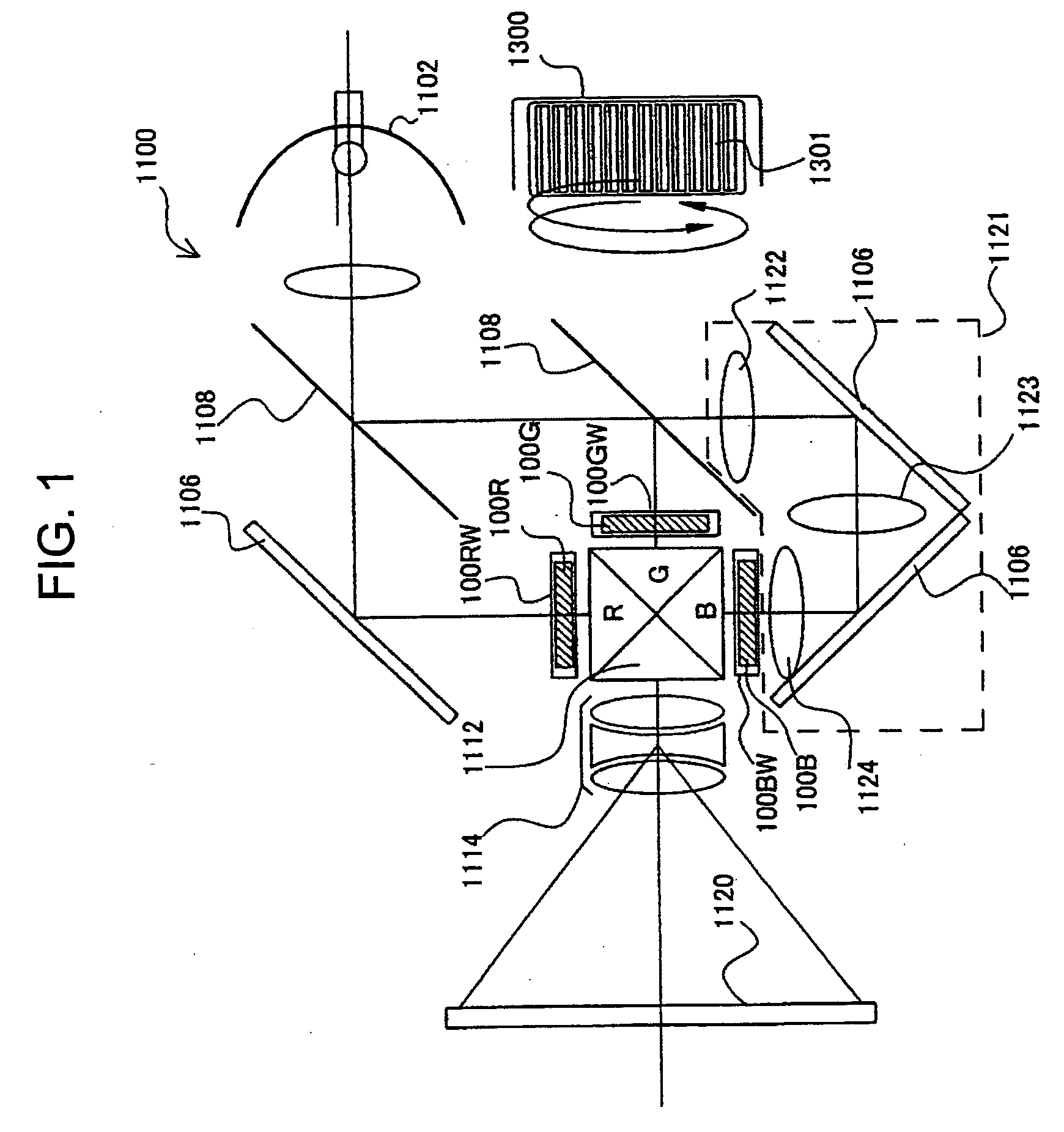
[0053] A structure of an electronic apparatus according to the present embodiment will be first described with reference to FIG. 1. FIG. 1 is a diagram schematically showing the structure of the electronic apparatus according to the present embodiment. Furthermore, in the present embodiment, a projection-type liquid crystal projector will be taken as an example of the electronic apparatus according to the invention.

[0054] In FIG. 1, a liquid crystal projector 1100 is composed of a multi-plate-type color projector using liquid crystal light valves 100R, 100G and 100B for RGB.

[0055] In the liquid crystal projector 1100, if projection light is emitted from a lamp unit 1102 of a white light source, such as a metal halide lamp, it is divided into light components R, G and B corresponding to three primary colors including RGB by means of ...


PUM

PropertyMeasurementUnit
electricalaaaaaaaaaa
flexibleaaaaaaaaaa
temperatureaaaaaaaaaa

Abstract

A mounting case for an electro-optical device accommodates an electro-optical panel that is used in the electro-optical device in which display images are displayed on the basis of electrical signals transmitted to and from the outside through the mounting case. The mounting case for an electro-optical device includes a body portion that is constructed to accommodate the electro-optical panel in a state in which one end of a flexible wiring board for transmitting the electrical signals is connected to the periphery of the electro-optical panel and which has a wall portion defining an opening through which the other end of the flexible wiring board leads from the inside to the outside of the mounting case. The wall portion has a cross-sectional shape that widens from the inside to the outside of the mounting case in a cross section crossing a surface of the flexible wiring board in a direction from the inside toward the outside of the mounting case.

Description

BACKGROUND OF THE INVENTION [0001] 1. Technical Field [0002] The present invention relates to a mounting case for mounting an electro-optical panel used in an electro-optical device, to an electro-optical device, such as a liquid crystal device, having the electro-optical panel, and to an electronic apparatus that uses the electro-optical device as a light valve. [0003] 2. Related Art [0004] This electro-optical panel is not installed in a casing body of a device as it is in a so-called panel state, but is installed in a state in which it is mounted or accommodated in a proper mounting case, when it is used as a light valve in an electronic apparatus, such as a liquid crystal projector. The reason why the electro-optical panel is accommodated in the mounting case is that the electro-optical panel can be easily fixed or attached to the casing body through screw holes by providing the screw holes in the mounting case. [0005] In such an electronic apparatus, projection light to the ele...

Claims


Application Information

Patent Timeline
Patent Type & Authority Applications(United States)
IPC IPC(8): G02F1/1333
CPCG02F1/13452
Inventor MIYASHITA, TOMOAKI
Owner SEIKO EPSON CORP
Why Eureka
Try Eureka