
Pickup lens with phase compensator and optical pickup apparatus using the same

a phase compensator and optical pickup technology, applied in the direction of optical recording heads, instruments, data recording, etc., can solve the problems of difficult to share components with the infinite optical system, hinder the achievement of a simple optical system, and wavefront aberration, so as to achieve simple optical system, prevent aberration, and reduce the effect of aberration

Inactive Publication Date: 2006-04-20
MAXELL HLDG LTD
View PDF6 Cites 4 Cited by
  • Summary
  • Abstract
  • Description
  • Claims
  • Application Information

AI Technical Summary

Benefits of technology

[0019] In view of the foregoing, it is an object of the present invention to solve the above problems. Specifically, an object of the present invention is to provide a pickup lens with a phase compensator that assures low wavefront aberration for each of a plurality of types of optical discs using different wavelengths with a simple optical system and prevents aberrations specific to finite system that is caused by misalignment of the optical axes of a condenser lens and incident light when performing tracking servo by an actuator, and an optical pickup apparatus using the same.
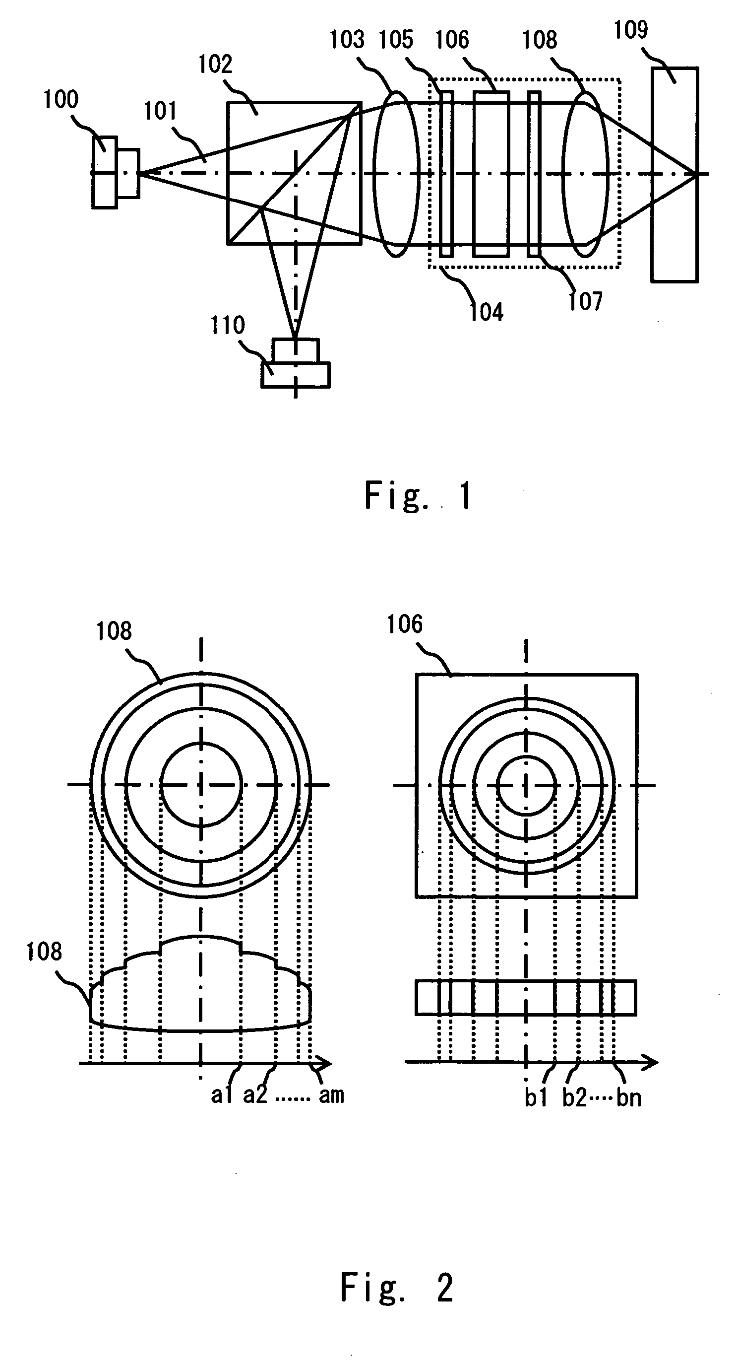
[0020] To these ends, according to an aspect of the present invention, there is provided a pickup lens with a phase compensator that is composed of a condenser lens and a phase compensator, wherein at least one surface of the condenser lens has a step-like annular zone structure to compensate wavefront aberration generated when recording and reproducing data on an information recording medium having a substrate thickness of t1 with a laser beam having a wavelength λ1 and wavefront aberration generated when recording and reproducing data on an information recording medium having a substrate thickness of t2 with a laser beam having a wavelength λ2, and the phase compensator compensates wavefront aberration generated when recording and reproducing data on an information recording medium having a substrate thickness of t3 with a laser beam having a wavelength λ3. This structure ensures reduction of wavefront aberration as much as possible for each of three different kinds of information recording media that use wavelengths λ1, λ2 and λ3 with a simple optical system.

Problems solved by technology

Because of aberrations caused by these reasons, use of a conventional condenser lens for both CD and DVD in the compatible optical disc apparatus fails to focus each laser beam used for CD and DVD on the information recording surface of each optical disc close to the diffraction limit.
On the other hand, since the condenser lens does not allow for the wavelength λ3, wavefront aberration occurs when recording or reproducing information on the third optical medium by using a laser beam with the wavelength λ3.
Specifically, though the technique taught by Ota et al. corrects aberrations by using the finite system when recording or reproducing information on the third optical medium with the wavelength λ3, it is difficult to share components with the infinite optical system used when recording and reproducing information on the second optical medium with a laser beam of the wavelength λ1 and when recording and reproducing information on the first optical medium with a laser beam of the wavelength λ2.
Further, in a case of using a three-wavelength laser having wavelengths of λ1, λ2 and λ3 as one element, it is difficult to make finite system only when recording and reproducing information on the third optical medium with a laser beam of the wavelength λ3, which hinders achievement of a simple optical system.
Furthermore, in a case of performing tracking servo by applying divergent light to a condenser lens and mounting the condenser lens onto an actuator, aberrations specific to the finite system that are caused by misalignment of the optical axis of the condenser lens and the optical axis of incident light occur, thereby failing to sufficiently focus laser beams on the information surface of an optical disc.
Further, use of the three-wavelength laser complicates the structure of the optical system.

Method used


Image

  • Pickup lens with phase compensator and optical pickup apparatus using the same
  • Pickup lens with phase compensator and optical pickup apparatus using the same
  • Pickup lens with phase compensator and optical pickup apparatus using the same

Examples


first embodiment

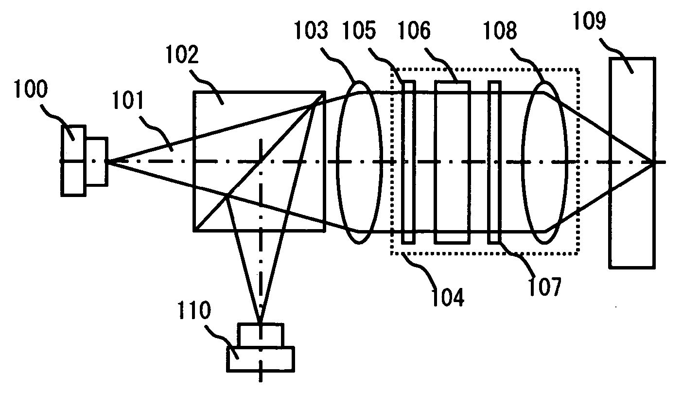
[0082] A first embodiment of the present invention is detailed hereinafter. FIG. 1 shows an example of an optical pickup according to the present invention. A three-wavelength laser 100 includes a light source for HD-DVD (wavelength=405 nm), a light source for DVD (wavelength λ=655 nm), and a light source for CD (wavelength λ=790 nm). The three-wavelength laser 100 outputs laser light 101 that is divergent light with a given divergent angle. The laser light 101 passes through a polarizing beam splitter 102 and enters a collimator lens 103 where it is converted to substantially parallel light. The parallel light then enters a lens module 104, which is a feature of the present invention, and focuses on an information recording surface of an optical disc 109 close to the diffraction limit. The laser beam reflected by the information recording surface of the optical disc 109 then enters the polarizing beam splitter 102 through the lens module 104. The laser beam is reflected by the pola...

second embodiment

[0101] A second embodiment of the present invention is described hereinafter in detail. The first embodiment requires an element which can be mechanically replaceably inserted in an optical path or whose operation can be electrically controlled as a phase compensator, and it uses a liquid crystal compensator as an example of such a phase compensator. The second embodiment eliminates the need for mechanically inserting or replacing a phase compensator in an optical path or electrically-controlling the operation of a phase compensator, thereby significantly simplifying the structure of the lens module of the present invention compared to the first embodiment.

[0102]FIG. 15 shows an example of an optical pickup according to the present invention. Briefly, a three-wavelength laser 100 includes a light source for HD-DVD (wavelength λ=405 nm), a light source for DVD (wavelength λ=655 nm), and a light source for CD (wavelength λ=790 nm). The three-wavelength laser 100 outputs laser light 1...

third embodiment

[0134] A third embodiment of the present invention is described hereinafter in detail. In the first and second embodiments, the surface of the condenser lens in the object side has a discontinuous aspherical shape. This shape is formed in order to reduce wavefront aberrations in recording or reproduction of HD-DVD and DVD as much as possible as described above. In the third embodiment, the surfaces of the condenser lens in the object side and the image side have a continuous aspherical shape, one side surface of the phase compensator has a discontinuous aspherical shape so as to reduce wavefront aberrations in recording or reproduction of HD-DVD and DVD as much as possible, and the other side surface of the phase compensator has an annular zone structure centering on an optical axis, each loop zone designed to give a different phase difference to light, so as to reduce wavefront aberrations in recording or reproduction of CD as much as possible.

[0135] The third embodiment is partic...


PUM

PropertyMeasurementUnit
thickness t3aaaaaaaaaa
wavelength λ3aaaaaaaaaa

Abstract

A pickup lens with a phase compensator is composed of a condenser lens and a phase compensator. At least one surface of the condenser lens has a step-like annular zone structure to compensate wavefront aberration generated when recording and reproducing data on an information recording medium having a substrate thickness of t1 with a laser beam having a wavelength λ1 and wavefront aberration generated when recording and reproducing data on an information recording medium having a substrate thickness of t2 with a laser beam having a wavelength λ2. The phase compensator compensates wavefront aberration generated when recording and reproducing data on an information recording medium having a substrate thickness of t3 with a laser beam having a wavelength λ3.

Description

BACKGROUND OF THE INVENTION [0001] 1. Field of the Invention [0002] The present invention relates to a pickup lens with a phase compensator that can be used for a multiwavelength optical system using a plurality of kinds of monochromatic light such as a compatible recording and reproduction apparatus that is compatible with different types of optical recording media such as compact discs (CDs) including CD-R, digital versatile discs (DVDs), Blu-ray and High-Definition DVD (HD-DVD) and an optical pickup using the same. [0003] 2. Description of Related Art [0004] Compatible optical disc apparatus capable of recording or reproducing data on different types of optical discs such as CD and DVD with one system have been proposed. [0005] In order to record or reproduce information signals stored on optical discs such as CD and DVD (which is hereinafter collectively called the optical disc), the compatible optical disc apparatus needs to focus a laser beam from a light source on an informat...

Claims


Application Information

Patent Timeline
Patent Type & Authority Applications(United States)
IPC IPC(8): G11B7/00G11B7/135
CPCG11B7/1369G11B7/13925G11B2007/0006G11B7/1367G11B7/1374
Inventor WAKABAYASHI, KOICHIROHIRAO, KEIKOMIYAUCHI, MITSUHIROMAKINO, YUTAKASUGI, YASUYUKIMITSUI, YOSHIKAZU
Owner MAXELL HLDG LTD
Learn More