
Battery sheath having radiation layer formed thereon and lithium polymer battery using the same

a lithium polymer battery and radiation layer technology, applied in the field of battery sheaths comprising radiation layers and lithium polymer batteries using sheaths, can solve the problems of reducing radiation performance, unable to effectively resist heat, reducing battery life, etc., to achieve rapid detection of temperature increases in the battery, increase the life and reliability of the battery, and maximize the radiation performance of the battery

Active Publication Date: 2006-04-20
SAMSUNG SDI CO LTD
View PDF6 Cites 48 Cited by
  • Summary
  • Abstract
  • Description
  • Claims
  • Application Information

AI Technical Summary

Benefits of technology

[0009] In one embodiment of the present invention, a battery sheath is provided having improved radiation performance in order to suppress temperature increases in the battery during charging and discharging. The battery sheath comprises a radiation layer on its surface. A positive temperature coefficient (PTC) device contacts the radiation layer, thereby improving the response of the PTC device. The battery sheath has improved mechanical strength, corrosion resistance and resistance to impact.
[0012] The battery sheath comprises a radiation layer on its surface. The radiation layer is both an electric insulator and a thermal conductor. The radiation layer maximizes radiation performance of the battery during charging and discharging and increases the life and reliability of the battery.
[0013] PTC device is connected between the protective circuit module and the electrode assembly and directly contacts the radiation layer of the battery sheath. This contact enables the PTC device to quickly detect temperature increases in the battery and interrupt or reduce current flow, thereby remarkably improving battery reliability.
[0014] Furthermore, the radiation layer on the battery sheath improves the mechanical strength of the battery and increases resistance to corrosion and impact.

Problems solved by technology

First, unlike lithium ion batteries, lithium polymer batteries can have a plate structure and need not be wound.
Third, the plate structure of lithium polymer batteries makes it unnecessary to apply pressure to form the square shape.
However, pouch type battery sheaths do not radiate heat well, thereby reducing the life of the battery.
These materials decrease radiation performance and cannot effectively withstand the heat generated during charging and discharging.
Furthermore, the amount of discharge increases as temperature rises, which drastically reduces battery life.
When the temperature of the battery rises above a threshold level, the electrode assembly or the electrolyte decomposes, generating a large amount of gas.
This gas generation increases the internal pressure of the battery and causes the battery to swell, seriously decreasing battery reliability.
The resistance of such a PTC device increases relative to temperature, and interrupts charging currents upon increases in temperature.
However, the battery sheath comprises nylon or PET on its surface, which decreases radiation performance as noted above, and heat generated inside the sheath is not quickly transmitted to the PTC device.
Accordingly, the PTC device fails to respond quickly to the rising temperature of the battery, seriously decreasing battery reliability.
In addition, conventional battery sheaths have low mechanical strength and are very vulnerable to external impact.
Also, the sheath is easily torn f bitten by a pet.
Furthermore, penetration of the sheath with a sharp object can cause a short circuit if the object contacts the internal electrode assembly.
As a result, the battery may catch fire or explode.

Method used


Image

  • Battery sheath having radiation layer formed thereon and lithium polymer battery using the same
  • Battery sheath having radiation layer formed thereon and lithium polymer battery using the same
  • Battery sheath having radiation layer formed thereon and lithium polymer battery using the same

Examples


Embodiment Construction

[0031] Exemplary embodiments of the present invention will now be described with reference to the accompanying drawings. In the following description and in the drawings, like reference numerals are used to designate like components in order to avoid repetitive descriptions of same or similar components.

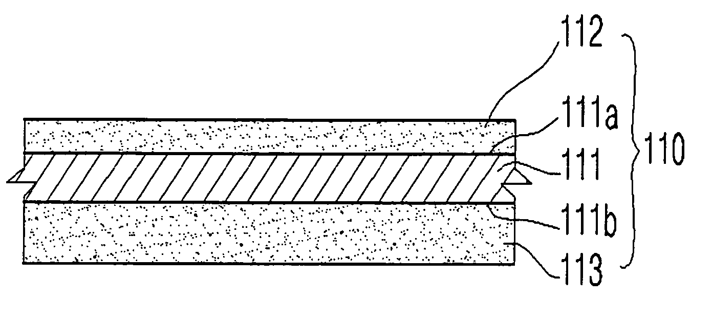
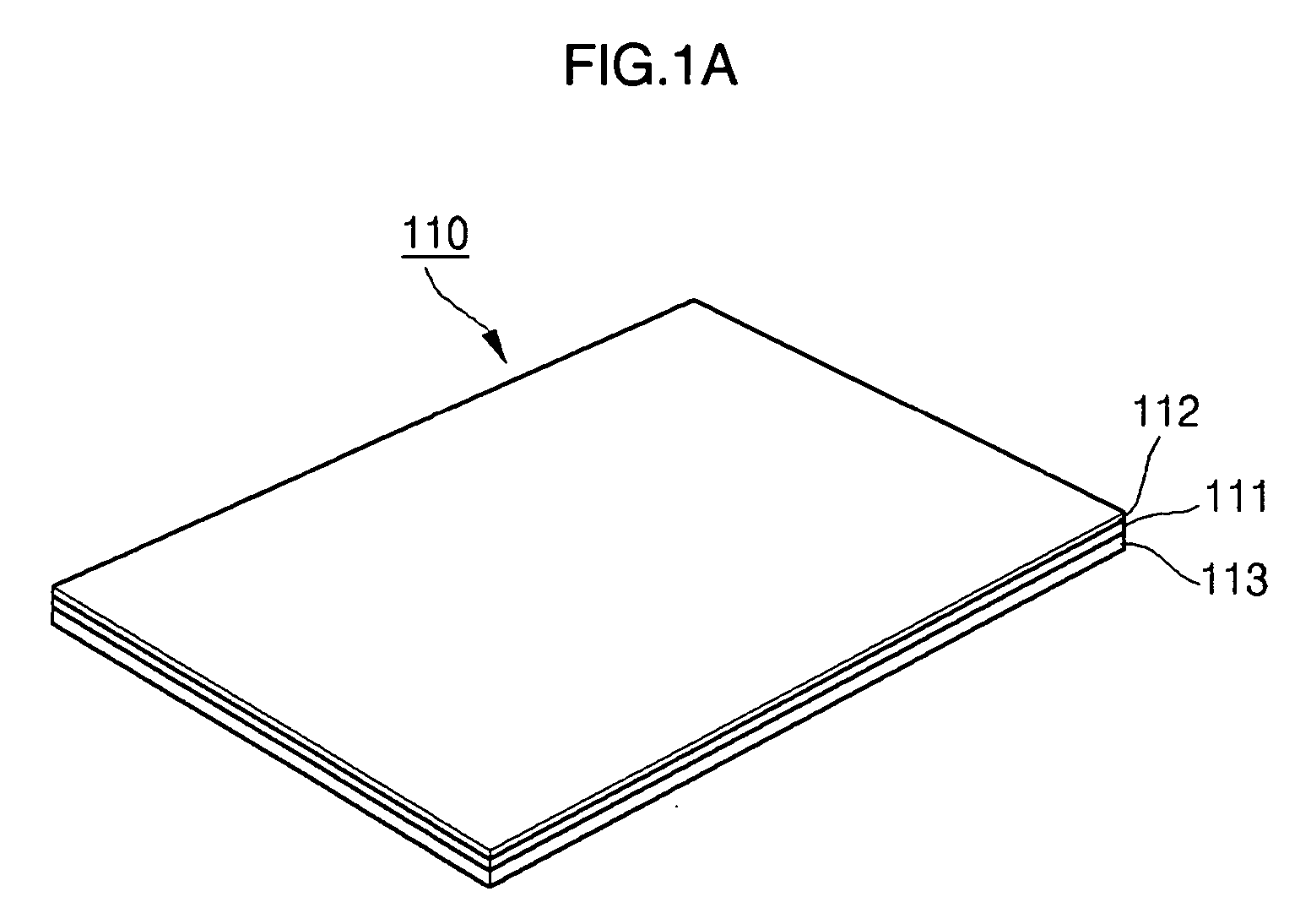
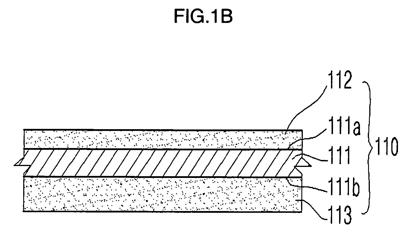
[0032]FIG. 1A is a perspective view of a battery sheath according to one embodiment of the present invention. FIG. 1B is a magnified cross-sectional view of the sheath of FIG. 1A. As shown in FIGS. 1A and 1B, a battery sheath 110 comprises a metal layer 111, a radiation layer 112, and a cast polypropylene (CPP) layer 113.

[0033] The metal layer 111 has a first surface 111a and a second surface 111b. The metal layer 111 has a thickness ranging from about 20 to about 100 μm. If the thickness of the metal layer 111 is less than about 20 μm, it may be easily fractured or damaged during processing. If the thickness of the metal layer is greater than about 100 μm, it is difficult to proce...


PUM

PropertyMeasurementUnit
volume %aaaaaaaaaa
thicknessaaaaaaaaaa
thicknessaaaaaaaaaa

Abstract

A battery sheath having a radiation layer on its surface and a lithium polymer battery using the sheath are provided. The radiation layer improves radiation performance and mechanical strength of the battery, and also improves the response of a PTC device. The battery sheath comprises a metal layer having first and second surfaces, a radiation layer on the first surface of the metal layer, and a cast polypropylene (CPP) layer on the second surface of the metal layer. The lithium polymer battery has a PTC device electrically connected to a protective circuit module. The PTC device directly contacts the radiation layer of the battery sheath, thereby improving the response of the PTC device.

Description

CROSS REFERENCE TO RELATED APPLICATION [0001] This application claims priority to and the benefit of Korean Patent Application No. 2004-0083275, filed Oct. 18, 2004 in the Korean Intellectual Property Office, the entire content of which is incorporated herein by reference. FIELD OF THE INVENTION [0002] The present invention relates to a battery sheath comprising a radiation layer and to a lithium polymer battery using the sheath. More particularly, the invention is related to a battery sheath that improves the radiation performance of lithium polymer batteries and the responses of positive temperature coefficient (PTC) devices to increases in temperature. BACKGROUND OF THE INVENTION [0003] As generally known in the art, a lithium polymer battery is a battery having an electrode assembly comprising a separator positioned between positive and negative electrode plates. The separator performs the role of the electrolyte, namely, it acts as a medium of ion conduction. In addition, the s...

Claims


Application Information

Patent Timeline
Patent Type & Authority Applications(United States)
IPC IPC(8): H01M2/02B32B15/085H01M10/05H01M10/052H01M10/0565H01M10/0587H01M10/60H01M10/613H01M10/647H01M10/653H01M50/117H01M50/119H01M50/121H01M50/122H01M50/126H01M50/129H01M50/133H01M50/136
CPCB32B3/26B32B5/16B32B15/06B32B15/08B32B15/085B32B15/16B32B15/18B32B15/20B32B25/20B32B27/32B32B2250/03B32B2260/025B32B2260/046B32B2264/102B32B2264/107B32B2307/206B32B2307/302B32B2307/54B32B2307/714B32B2457/10H01M2/0257H01M2/0275H01M2/0287H01M2/0295H01M6/181H01M10/052H01M10/0525H01M10/0565H01M2200/106Y02E60/122Y10T428/31692Y02E60/10H01M50/124Y02P70/50H01M50/126H01M50/133H01M50/121H01M50/129H01M50/136H01M50/117H01M50/122H01M50/119
Inventor OH, JEONG WONSOHN, YOUNG BAE
Owner SAMSUNG SDI CO LTD
Learn More