Overload Protection Device and Machine Tool Having Such Overload Protection Device

a protection device and overload protection technology, applied in automatic clutches, grinding machines, mechanical equipment, etc., can solve the problems of shaft decoupling, shaft decoupling, and operator inability to act fast enough to actuate such couplings, etc., to achieve safe starting behavior, reduce wear, and increase torque

Active Publication Date: 2006-04-20
ATLAS COPCO ELECTRIC TOOLS
View PDF10 Cites 22 Cited by
  • Summary
  • Abstract
  • Description
  • Claims
  • Application Information

AI Technical Summary

Benefits of technology

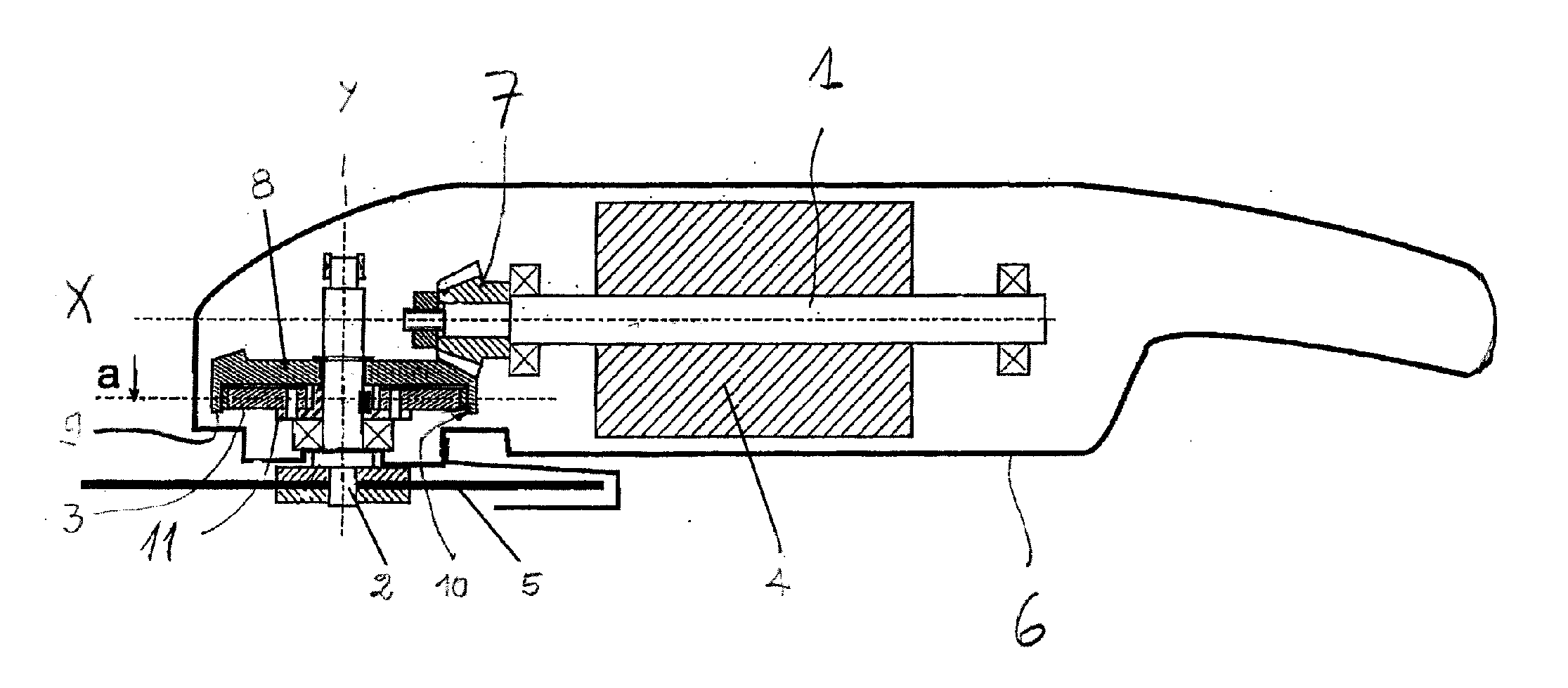
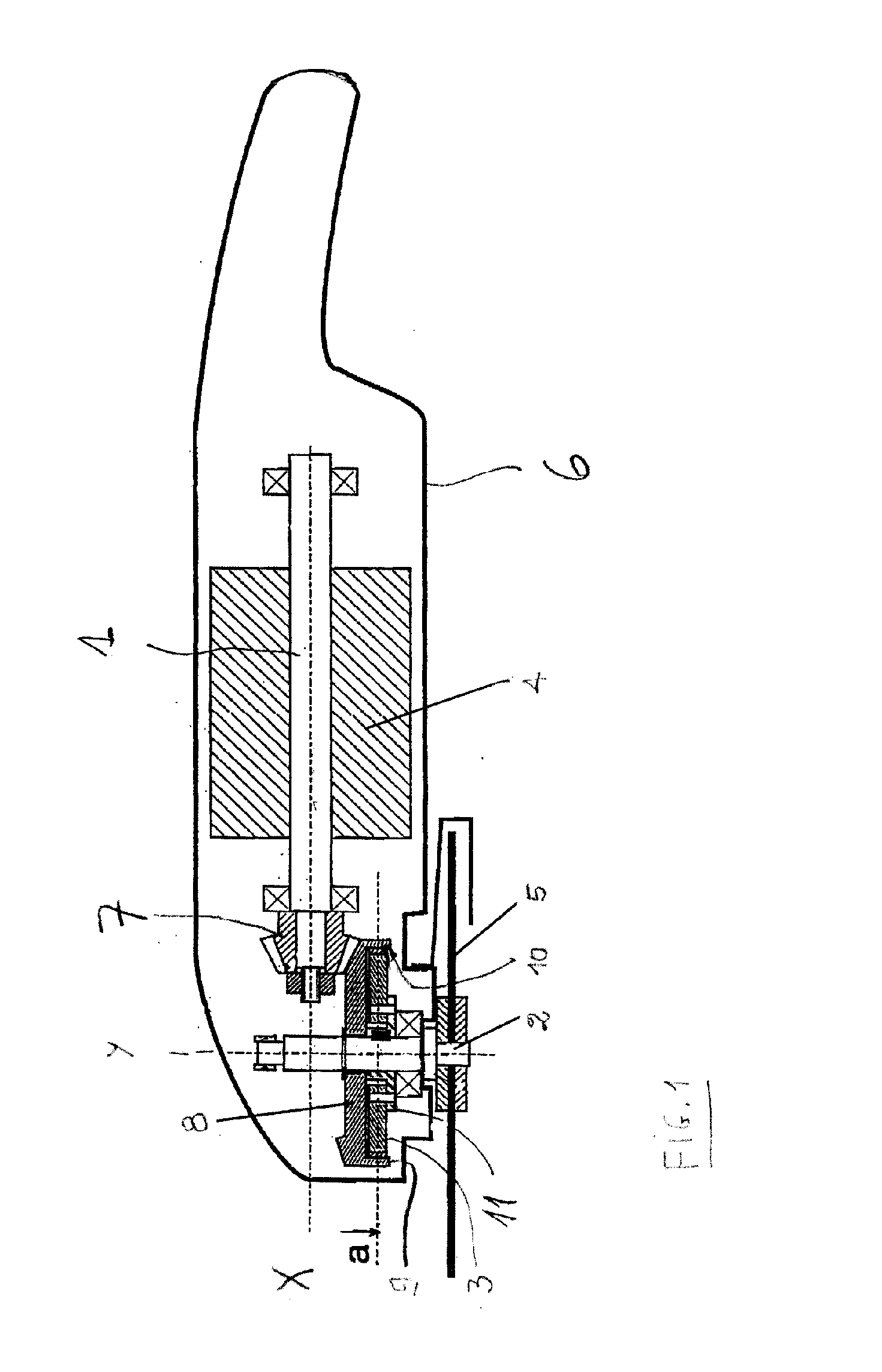
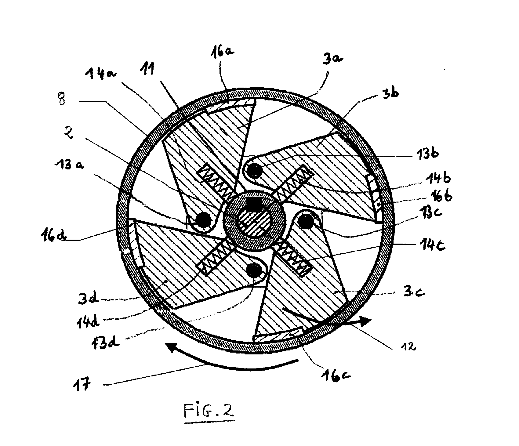
[0041] Advantageously, in addition or as an alternative, a radial inner stop can be provided for the fly body wherein a radial outer friction coating of the fly body is forced against the circumferential wall by means of the stop. In this connection, elastic material properties of the friction coating will be taken advantage of. The friction coating with regard to elasticity and shape is configured such that in the rest position it rests with slight clamping action on the drum. The slight clamping action has the effect, on the one hand, of a safe starting behavior and enables, on the other hand, in a blocking situation of the tool a jerk-free slipping.
[0042] In an advantageous configuration, a support member is provided with a bearing leg wherein the fly body has two securing legs that engage like a fork the bearing leg. A hinge pin extends through the bearing leg and the securing legs. In this way, a symmetric two-sided pivot support of the fly body is provided that is essentially free of canting effects. The lateral glide surfaces between the bearing leg and the securing legs provide an additional guiding action. The desired alignment of the flyweight remains intact even under high operating loads. For a given size of the device a higher torque can be transmitted while wear is reduced.
[0043] In the case of a pivoting support, the fly body has expediently positive-engaging guide means at its free pivoting end. In addition to the guiding action on the hinge bearing, a position fixation of the fly body with guiding action is also provided on the opposite free end. The positional precision of the fly body relative to the drum is further improved.
[0044] In an advantageous configuration, the fly body is pivotably supported in a hinge bearing wherein its free end, beginning at the hinge bearing, points in an operational rotary direction of the drum. This provides a so-called trailing arrangement of the fly body. The rotation of the drum in its operational rotary direction does not lead to a self locking action by means of frictional contact with the fly body. Instead, the frictional force on the fly body has a force component relative to the pivot bearing that is directed inwardly in the pivot direction. During usual operation, this inwardly oriented force component is compensated by the outwardly orie

Problems solved by technology

In the case of a strong overload of the output shaft as is the case when the tool is blocked, the operator cannot act fast enough in order to actuate such a coupling.
Such a system, however, does not operate automatically for decoupling, and blockage of the tool does not cause the two shafts to be decoupled.
Such a device has the disadvantage that the entire additional energy is essentially dissipated in the form of heat and that an excessive wear of the friction parts results because they continue to operate as long as the device is under load, i.e., as long as the motor rotates and the torque limit is surpassed.
Such a device has the disadvantage that the energy is lost in the form of noise and/or heat.
The device remains active as long as the torque is maintained; this cau

Method used


Image

  • Overload Protection Device and Machine Tool Having Such Overload Protection Device
  • Overload Protection Device and Machine Tool Having Such Overload Protection Device
  • Overload Protection Device and Machine Tool Having Such Overload Protection Device

Examples


first embodiment

[0087]FIG. 4 shows such an elastic device 23. In this embodiment, the driving means 3a-3d is attached by a leaf spring 24 on the output shaft 2. The leaf spring 24 is outwardly prestressed in order to fulfill the function of the spring device. It can also be prestressed in the other direction when it is supposed to fulfill the function of a return device.

second embodiment

[0088] such an elastic device 23, as illustrated in FIG. 5, resides in the use of an elastomer member 25. The elastomer member 25 arranged between the output shaft 2 and driving means 3a-3d serves, on the one hand, for their attachment to one another, wherein the widening movement 12 of the driving means 3a-3d is enabled because of the elasticity of the elastomer member 25. On the other hand, it fulfills the function of a spring device in order to force the driving means 3a-3d against the drum 8. Optionally, it can also take on the function of a return device that returns the driving means 3a-3d toward the shaft 2.

[0089] In FIG. 6, a further embodiment of the invention is illustrated. The opposed surfaces of the drum 8 and of the means 3A-3D have in a plane that extends transversely to the shaft 2 complementary profiles 20 that mesh with one another and generate a resistance in regard to the relative movement. This enables the transmission of drive torque between these surfaces and ...


PUM


Abstract

A portable device having an overload protection device for motor-operated tools has a drive motor, a drive shaft connected to the drive motor and driven in rotation by the drive motor, and an output shaft for driving a cutting tool, wherein the output shaft is arranged substantially perpendicularly to the drive shaft. A drive pinion is connected to the drive shaft. A drum is supported on the output shaft and driven in rotation by the drive pinion. A coupling is arranged between the drum and the output shaft and engages the drum. The coupling is connected to the output shaft. When the output shaft is blocked, the coupling effects an automatic decoupling between the drum and the output shaft in order to prevent overloading of the drive motor.

Description

BACKGROUND OF THE INVENTION [0001] 1. Field of the Invention [0002] The invention relates to a portable device comprising an overload protection device for motor-operated tools. The portable device comprises a drive shaft (input shaft) connected to a drive motor and rotatably driven by it, a driven shaft (output shaft) for driving a cutting tool and arranged essentially perpendicularly to the drive shaft, as well as a drum supported on the output shaft and driven in rotation by a drive pinion. The invention further relates to an overload protection device for an electrically driven machine tool, such as an angle grinder or the like. The overload protection device is arranged within a drive train between a tool and an electric motor driving the tool, wherein the machine tool has a gearbox. The invention also relates to an electrically driven machine tool such as an angle grinder having such an overload protection device. [0003] 2. Description of the Related Art [0004] In the prior ar...

Claims


Application Information

Patent Timeline
IPC IPC(8): B24B27/08
CPCB24B23/028B24B55/00B25B23/141F16D43/14F16D43/211F16D43/18F16D2043/145
Inventor ROBIEU, THOMASMARET
Owner ATLAS COPCO ELECTRIC TOOLS
Why Eureka
Try Eureka