Heat exchanger and method of manufacturing the same

a technology of heat exchanger and heat exchanger body, which is applied in the direction of manufacturing tools, soldering devices, light and heating equipment, etc., can solve the problems of fluid leakage from the heat exchanger, easy to occur joint defects, etc., and achieve the effect of enhancing the joint reliability of the tub

Inactive Publication Date: 2006-04-27
DENSO CORP
View PDF15 Cites 34 Cited by
  • Summary
  • Abstract
  • Description
  • Claims
  • Application Information

AI Technical Summary

Benefits of technology

[0005] In view of the above-described disadvantage, it is an object of the present invention to provide a heat exchanger and a manufacturing method thereof, to improve a joint reliability of a tube of the heat exchanger while an arrangement performance of an inner fin in the tube can be maintained.
[0007] Thus, the inner fin can be inserted in the tube from the side of this major-axis direction end, before the joint is formed. Moreover, because the tube is provided with the single joint which can be positioned at the one major-axis direction end, a joint reliability of the tube is enhanced.
[0009] Thus, the above-described heat exchanger can be manufactured. That is, the inner fin can be inserted in the tube from the side of the major-axis direction end, before the joint is formed. Moreover, the tube can be formed to have the single joint which is positioned at the one major-axis direction end. Therefore, the joint reliability of the tube can be enhanced.

Problems solved by technology

However, because the flow of the brazing material in the brazing is not satisfactory at the position where there exists a relatively large gap between the plates due to a plate distortion or the like, a joint defect easily occurs.
Thus, a fluid leakage from the heat exchanger may be caused.

Method used


Image

  • Heat exchanger and method of manufacturing the same
  • Heat exchanger and method of manufacturing the same
  • Heat exchanger and method of manufacturing the same

Examples


first embodiment

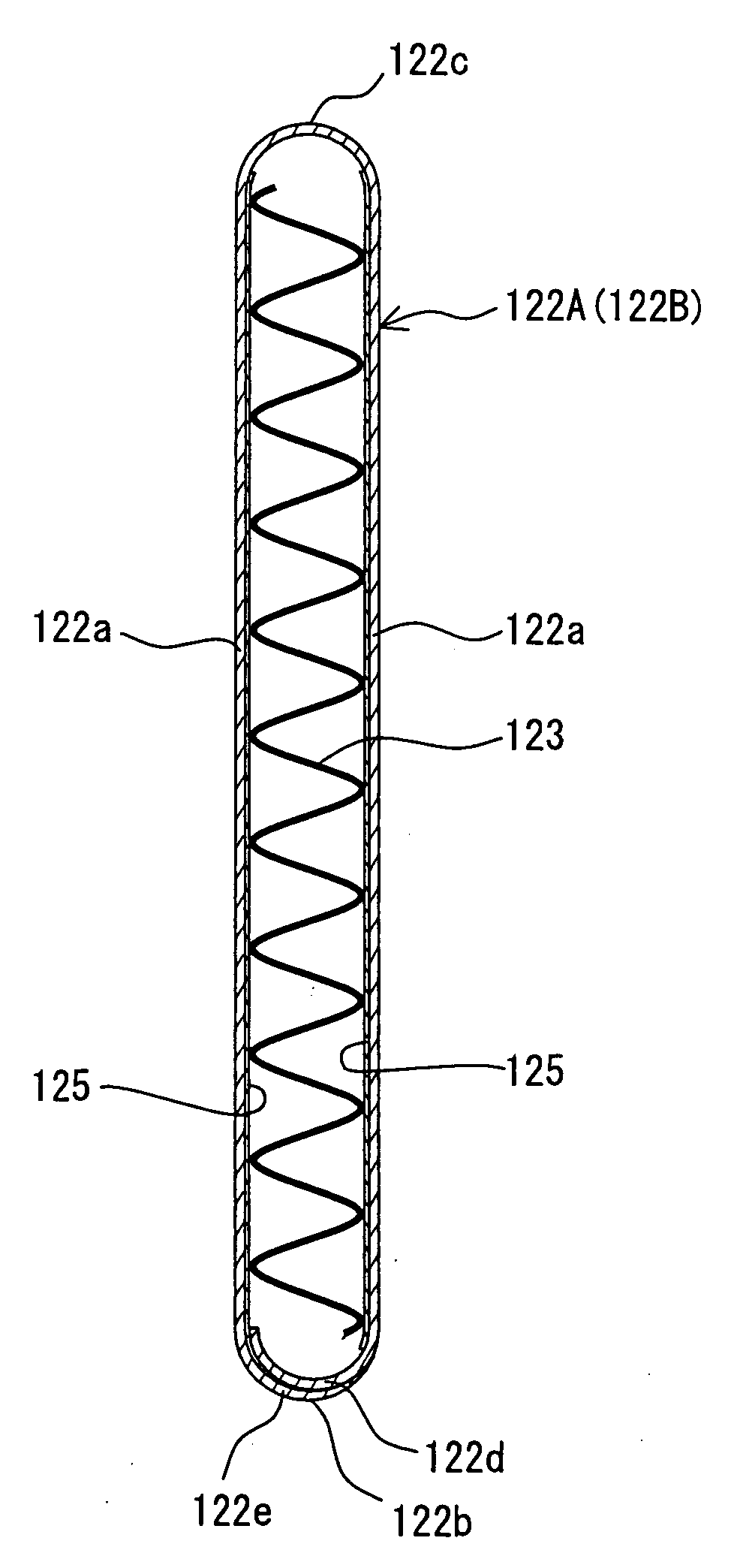
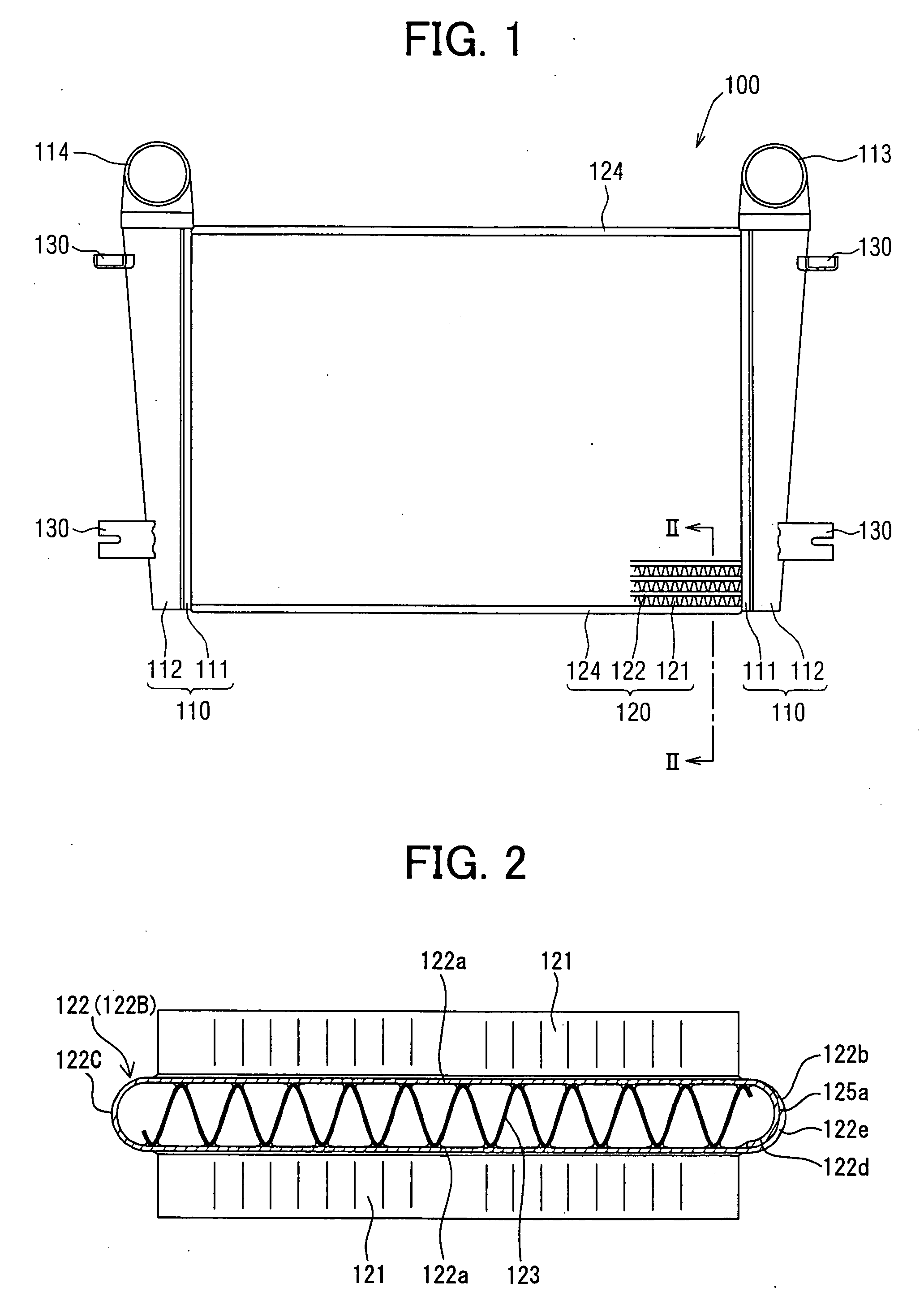
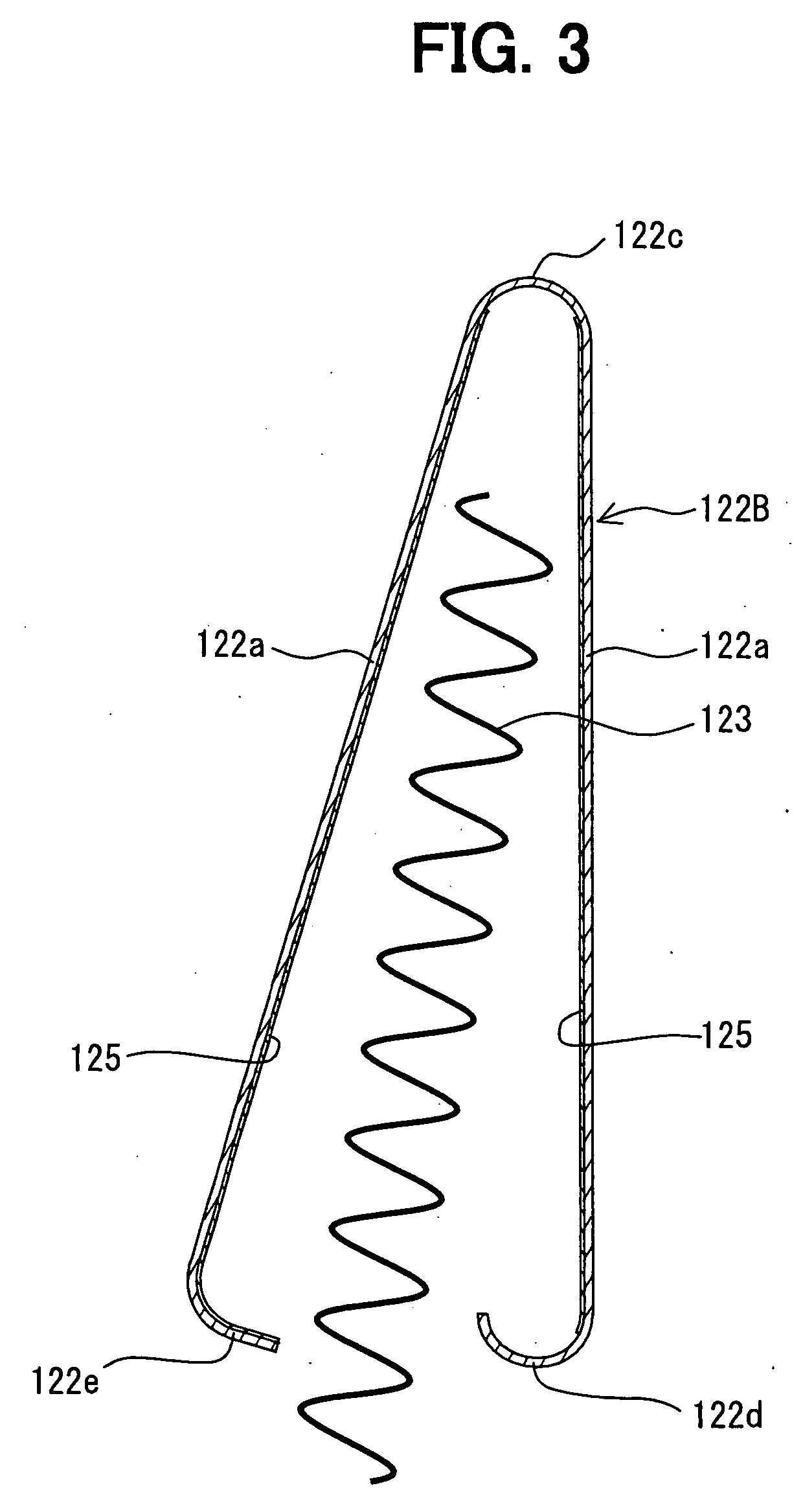
[0019] A first embodiment of the present invention will be described with reference to FIGS. 1-6. Referring to FIG. 1, a heat exchanger 100 (e.g., intercooler) is provided with a core member 120 and a pair of header tanks 110, which are respectively mounted at two ends (of longitudinal direction of tube 122 described later) of the core member 120. Each of the header tanks 110 has a hollow construction, and includes a core plate 111 and a tank portion 112 which are made of a copper alloy or the like and integrally joined by welding or brazing, for example.

[0020] One (e.g., at right side in FIG. 1) of the header tanks 110 is provided with an inlet joint 113 communicated with the interior of the one header tank 110. The other of the header tanks 110 (e.g., at left side in FIG. 1) is provided with an outlet joint 114 communicated with the interior of the other header tank 110. The inlet joint 113 can be connected with a discharge side of a supercharger (not shown), and the outlet joint...

second embodiment

[0055] A second embodiment of the present invention will be described referring to FIGS. 7 and 8. In this case, a joint 225 at the bend portion 122b of the tube 122 is formed by welding.

[0056] In the second embodiment, the forming process of the tube body 122A is performed after the arranging process of the inner fin 123 is performed. That is the same with the above-described first embodiment.

[0057] Referring to FIG. 7, in the forming process of the tube body 122A, the second edge portion 122e is revolved toward the first edge portion 122d (i.e., toward right side in FIG. 7), so that the second edge portion 122e contacts the first edge portion 122e. Then, the first edge portion 122d is temporarily fixed to the second edge portion 122e to construct the arc-shaped bend portion 122b. In this case, a tip 122g of the second edge portion 122e is not prolonged (deformed).

[0058] Then, referring to FIG. 8, the joining process of the tube body 122A is performed. In this case, the tip 122g ...


PUM

PropertyMeasurementUnit
widthaaaaaaaaaa
lengthaaaaaaaaaa
thicknessaaaaaaaaaa

Abstract

A heat exchanger includes at least one tube provided with an inner fin in a fluid passage which is defined by the tube therein and has a substantially ellipse-shaped cross section. A plate member for constructing the tube has two edge portions, which overlap each other and are integrally joined at a single joint disposed at a major-axis direction end of the tube. The inner fin is arranged in the tube before the forming of the joint, thus improving an arrangement performance of the inner fin. Moreover, there exists the single joint positioned at the one end of the tube so that a joint reliability of the tube is enhanced.

Description

CROSS REFERENCE TO RELATED APPLICATION [0001] This application is based on a Japanese Patent Application No. 2004-309939 filed on Oct. 25, 2004, the disclosure of which is incorporated herein by reference. FIELD OF THE INVENTION [0002] The present invention relates to a heat exchanger and a method of manufacturing the heat exchanger, in which a tube is provided with an inner fin therein. BACKGROUND OF THE INVENTION [0003] Generally, an inner fin can be arranged in a tube of a heat exchanger, for example, referring to JP-2003-28586A. In the manufacture of the heat exchanger, a pair of plates having a substantially ⊃-shaped cross section are confronted with each other to be engaged, while the inner fin is positioned therebetween. Thereafter, a joining of the two plates and a joining of the inner fin to the two plates are performed by brazing through a brazing material paste, which is applied to surfaces of the two plates. Thus, the tube in which the inner fin is joined to an inner sur...

Claims


Application Information

Patent Timeline
Patent Type & Authority Applications(United States)
IPC IPC(8): F28F1/40B21D21/00
CPCB21D53/02B23K1/0012B23K26/20B23K2201/08Y10T29/49391B23P15/26F28D1/0391F28F3/025B23K2201/14B23K26/244B23K2101/02B23K2101/06B23K2101/08B23K2101/14
Inventor UEDA, NAOKI
Owner DENSO CORP
Why Eureka
Try Eureka