
Baggage weight monitoring and theft protection

a technology for theft protection and baggage weight monitoring, applied in the field of baggage weight monitoring and theft protection, can solve problems such as the redesign of bags

Inactive Publication Date: 2006-04-27
KHAN FIRDOUS +1
View PDF2 Cites 15 Cited by
  • Summary
  • Abstract
  • Description
  • Claims
  • Application Information

AI Technical Summary

Benefits of technology

[0006] IMPROVEMENTS—THEFT PROTECTION: The system proposed has three major advantages over prior techniques: It gives an early warning the moment the baggage is picked up, it is simple to implement and because the circuits are only activated when the bag is picked up, battery life is practically equal to its shelf life—over 10 years when the latest lithium ion cells are used. DETAILS
[0009] In the case the transducers are fitted in the handle of the suitcase or bag, only the handle and its anchoring have to be redesigned, thus reducing costs.
[0010] In the theft protection mode the system is preferably designed so that the alarm signal is relayed to an external device such as a cellular phone. False alarms can be eliminated by using a unique 32-bit identification code for each transmitter-receiver pair. And by employing the internationally allocated 868 MHz frequency band, the transmitter-receiver link can be reliably maintained at ranges of up to 300 m even when using transmitter powers in the 10 mW range.
[0011] State of the art semiconductor technology will allow multiple functions to be combined on a single semiconductor chip thus reducing both space and electric energy requirements.
[0012] A unique feature of the proposed system is that all circuits are in the “off” state until the bag is picked up, thus ensuring high availability and long operational life.

Problems solved by technology

The advantage of the wired link is that both modules can use a common electric power source; its disadvantage is that the wires have to be embodied in the case, thus necessitating redesign of the bag.

Method used


Image

  • Baggage weight monitoring and theft protection
  • Baggage weight monitoring and theft protection
  • Baggage weight monitoring and theft protection

Examples


second embodiment

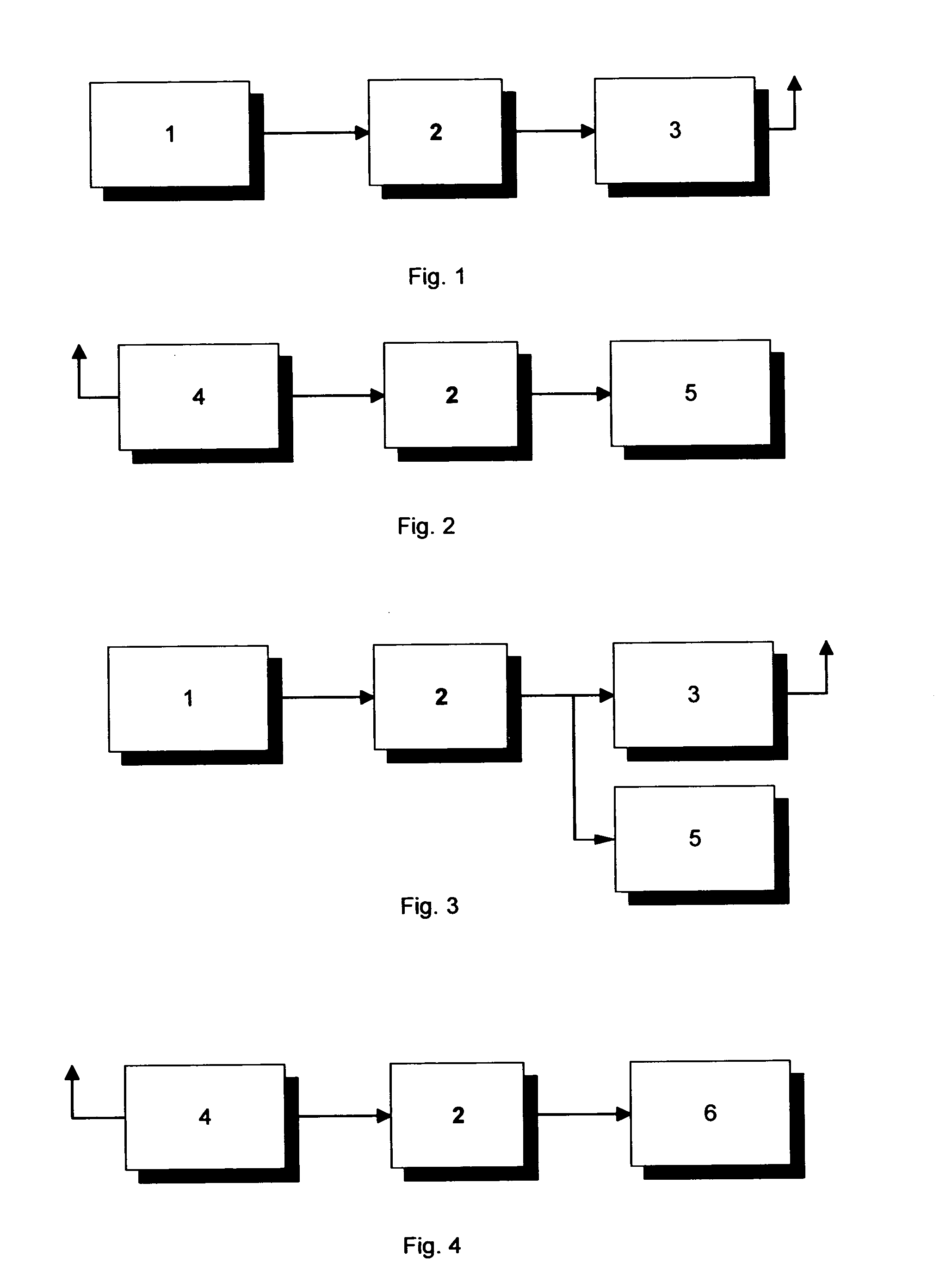
[0016]FIG. 3— Transducer (1), signal processor (2), transmitter (3) and display modules (5) all built into the baggage handle.

[0017]FIG. 4—Alarm processing modules in an external device, e.g. cellular phone: receiver (4), signal processor (2) and alarm processor (6).

first embodiment

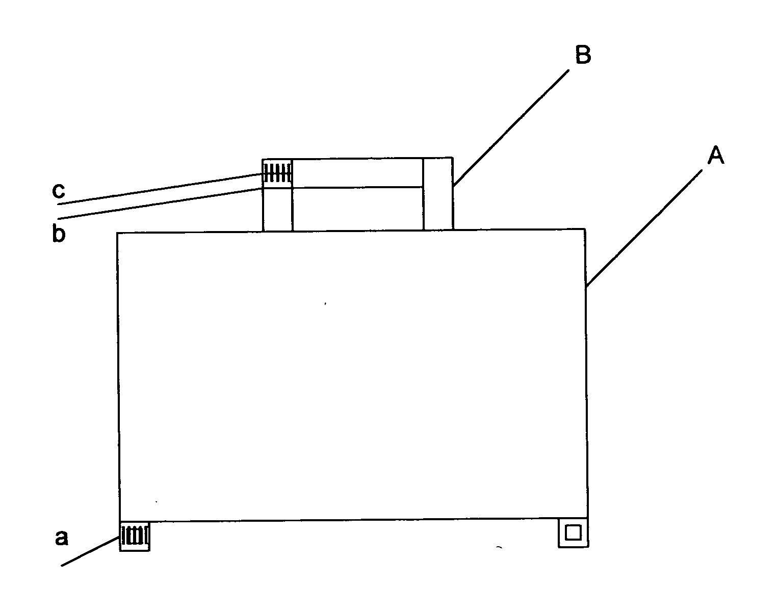
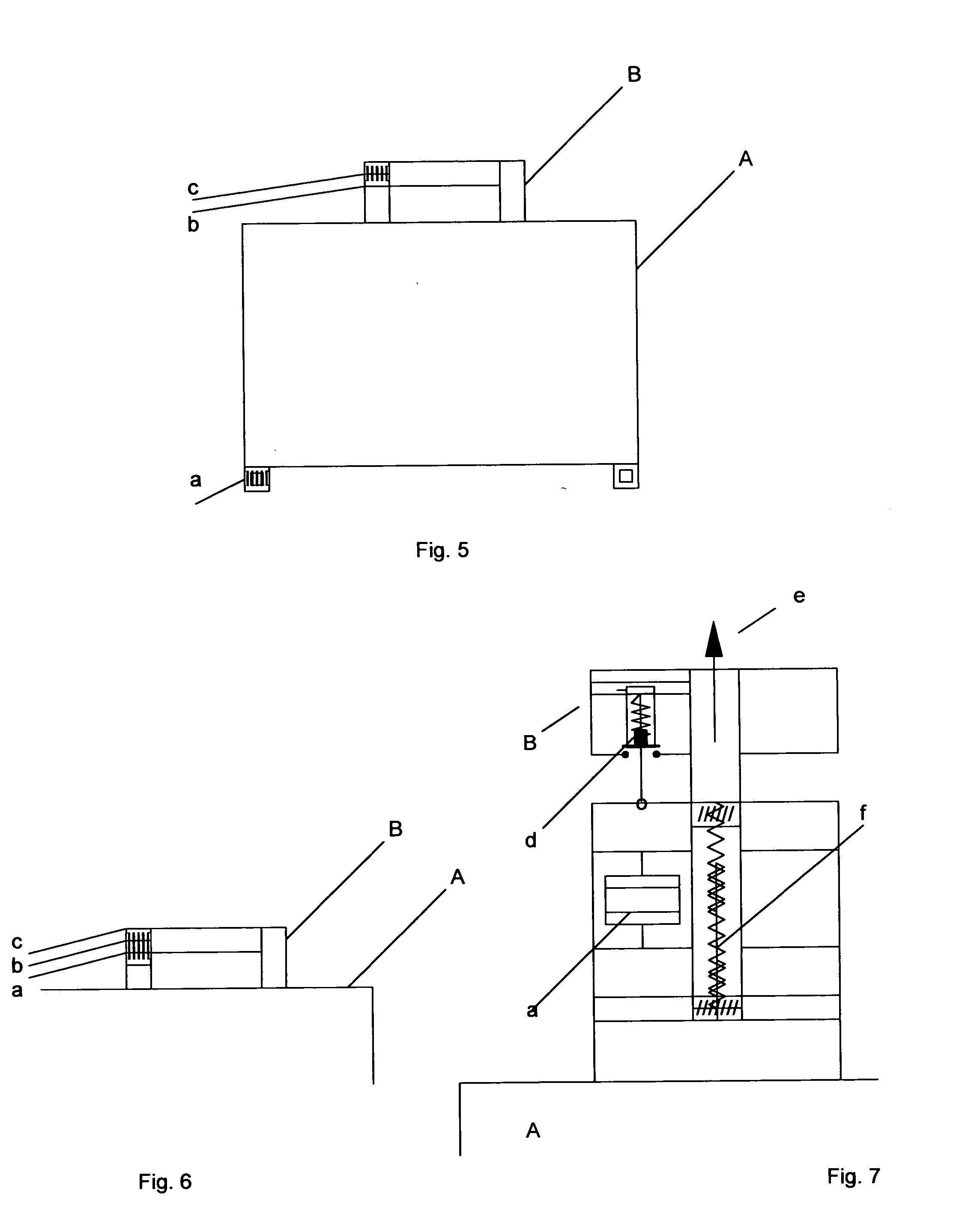
[0018]FIG. 5—Mechanical layout of modules in the The combined transducer, signal processor and transmitter module (a) is located in the bottom of the baggage (A) and the combined receiver and signal processor (b) as well as the display unit (c) are located in the handle (B).

[0019]FIG. 6—Mechanical layout of modules in the second embodiment: All modules are located on top of the bag (A), ideally within the handle (B). Transducer and signal processor are located in the anchoring (a), the transmitter (b) at the bottom of the handle, and the display (c) on top.

[0020]FIG. 7—Exemplary combination of a piezoelectric transducer (a), its associated pre-loading bolt (f), and on-off switch (d) in the handle (b). Normally in the off-state, the switch is actuated by the lifting force (e) which is equal to the weight of the bag (A).


PUM


Abstract

As weight restrictions become more stringent, air, train and bus passengers are being faced with the increasing cost of excess baggage weight. The proposed system makes use of transducers built into the bag or its handle both for weight monitoring and for theft protection. In the weight monitoring mode, designed for use during packing, an excess weight alarm is triggered when a preset maximum value is exceeded. In the theft protection mode, the transducer signal triggers an alarm as soon as the bag is picked up, thus giving early warning of possible theft. In this mode the signal is preferably transmitted to an external device such as a cellular phone for remote audible and / or visible indication. Because the circuits are switched on only when the suitcase or bag is picked up, battery life is practically equal to shelf life, hence ensuring high system availability.

Description

BACKGROUND OF THE INVENTION [0001] This invention relates to a system for baggage weight monitoring and theft protection using transducers such as load cells, strain gages, etc. built into the suitcase or bag. In the weight monitoring mode the system displays the weight of the bag thus facilitating packing. When a preset maximum weight is exceeded, an excess weight monitor signals this audibly and visually. In the theft protection mode, the system triggers an alarm indicating that the suitcase, bag or other baggage has been picked up, thus giving a reliable early warning of possible theft. DETAILED DESCRIPTION OF THE INVENTION [0002] PRIOR ART—WEIGHING: The majority of known baggage weighing systems are intended for use by transport facilities such as airport check-in counters and hence are based on external measurement. No specialized equipment is available for use at home or en route, hence travelers often have no opportunity to check for excess weight until the luggage is weighed...

Claims


Application Information

Patent Timeline
IPC IPC(8): G01G19/58G01G23/18B65D85/18
CPCA45C13/24A45C13/28G01G19/58G01G23/3728G08B13/1472
Inventor KHAN, FIRDOUSSHAH, RAYMOND
Owner KHAN FIRDOUS
Learn More