
Method and device for laser drilling in a process gas atmosphere

a laser drilling and process gas technology, applied in plasma welding apparatus, welding/soldering/cutting articles, manufacturing tools, etc., to achieve the effect of easy control or regulation

Active Publication Date: 2006-04-27
ROBERT BOSCH GMBH
View PDF5 Cites 8 Cited by
  • Summary
  • Abstract
  • Description
  • Claims
  • Application Information

AI Technical Summary

Benefits of technology

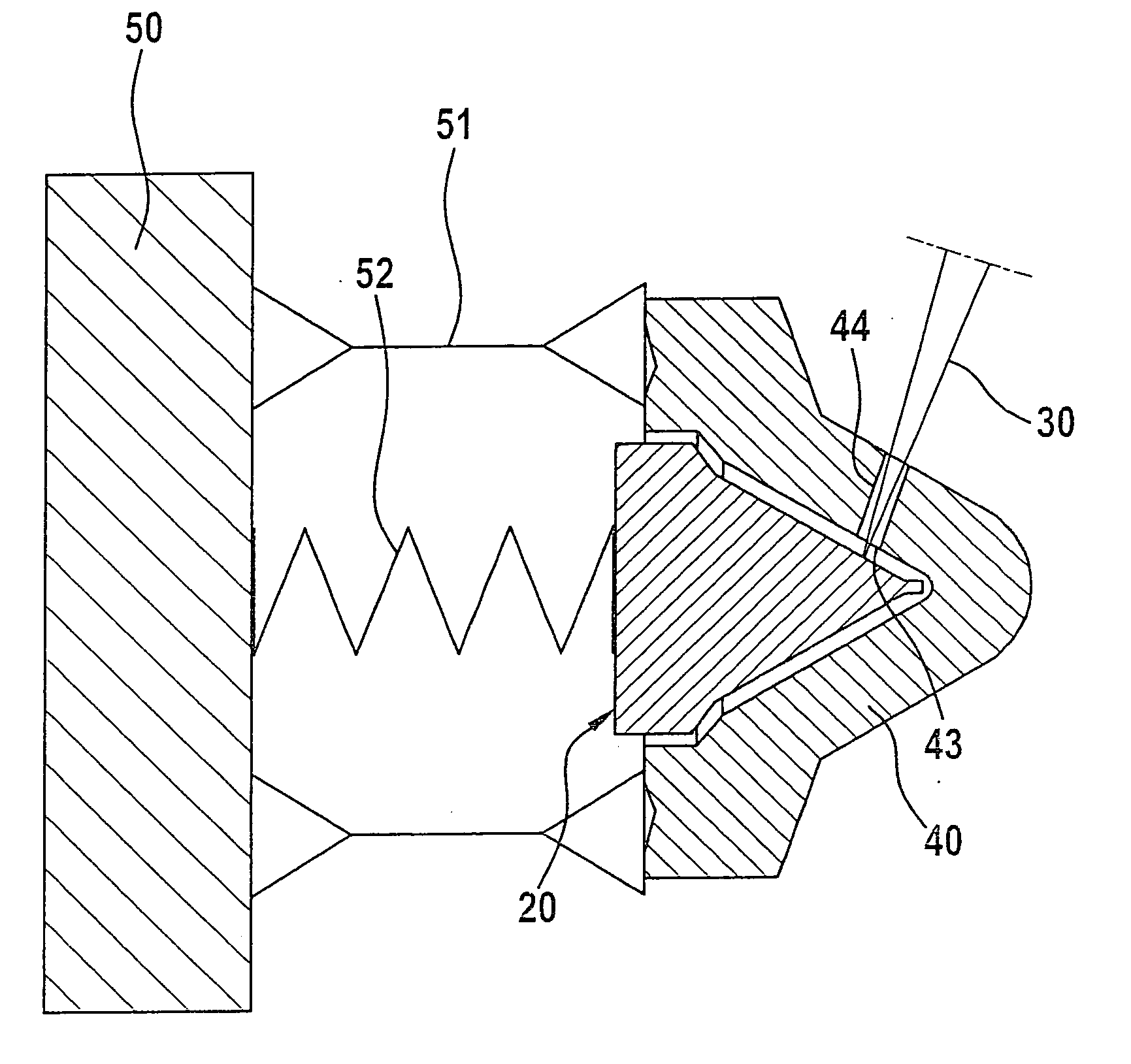
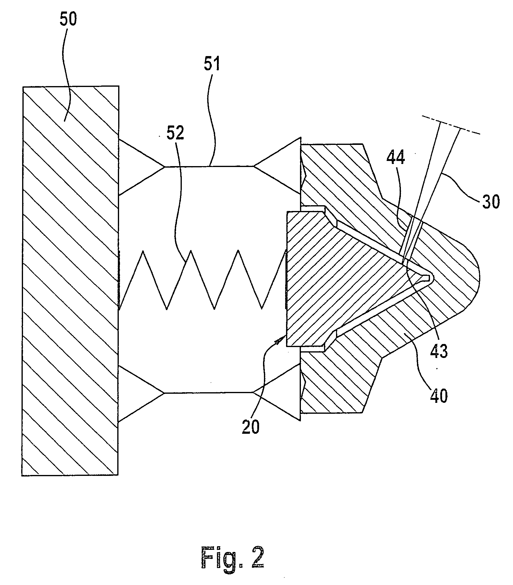
[0007] The present invention is intended to selectively influence the profile of the outlet of the bore hole (fuel intake) during the drilling operation using short-pulse (ns) or ultra-short pulse (ps / fs) lasers. In particular, a simple and low-cost production of various symmetrical and asymmetrical outlet profiles is provided, such profiles including, for instance, widened regions and bulges.

Problems solved by technology

Furthermore, laser drilling also allows the production of precision holes having diameters of less than 120 μm, but this has not yet been introduced as large-scale method.

Method used


Image

  • Method and device for laser drilling in a process gas atmosphere
  • Method and device for laser drilling in a process gas atmosphere
  • Method and device for laser drilling in a process gas atmosphere

Examples


Embodiment Construction

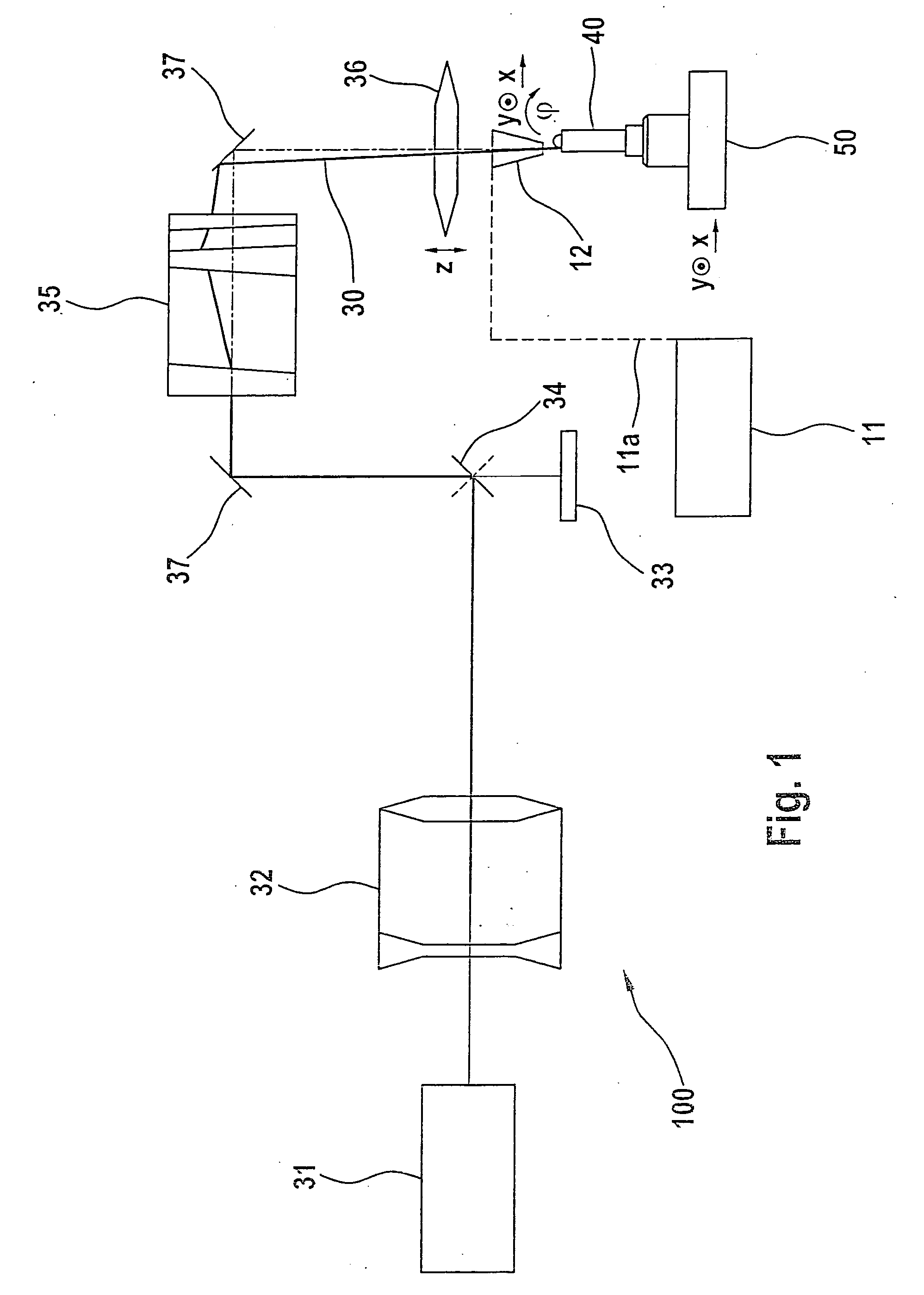
[0032] The illustrated specific embodiment of the device according to the present invention is designated as a whole by 100. A laser beam 30 generated by a laser 31 first traverses an expanding lens 32. Laser beam 30 is partially reflected or switched at a shutter 34, scattered or excess residual radiation being absorbed by a radiation sink 33. The direction of laser beam 30 inside its optical path is deflected by one or a plurality of mirrors 37. A trepanning lens 35 is also disposed inside the optical path, and the device for focusing the laser beam also has a focusing lens 36. In addition, the optical path of laser beam 30 runs through a gas nozzle 12 and impinges upon a workpiece 40 to be processed.

[0033] The process gas required to implement the method according to the present invention is provided by a gas mixer 11 and forwarded to a gas nozzle 12 via a line 11a. The process gas is blown directly onto workpiece 40 with the aid of a gas nozzle 12.

[0034] Workpiece 40 is mounte...


PUM

PropertyMeasurementUnit
pressureaaaaaaaaaa
tilting angleaaaaaaaaaa
distanceaaaaaaaaaa

Abstract

A method and device for laser drilling in which the geometric form of the drill-hole wall is influenced by reciprocal action between a laser beam and a supplied process gas, which thereby is ionized to plasma. Furthermore, the outlet opening of the drill hole is influenced by a suitable arrangement of a backing.

Description

BACKGROUND INFORMATION [0001] Precision micro-holes in nozzles of fuel-injection systems are usually introduced with the aid of erosion methods. Using this technology, it is currently possible to produce minimal diameters of approximately 120 μm in large-scale production. Furthermore, laser drilling also allows the production of precision holes having diameters of less than 120 μm, but this has not yet been introduced as large-scale method. [0002] In the fuel-injection field, there is increasing demand for conical holes to the effect that a fuel-outlet orifice have a smaller diameter than a fuel-intake orifice. Such precision micro-holes are already utilized in systems for diesel fuels (direct injection) or for gasoline (manifold and direct injection). [0003] German Patent No. DE 199 055 71 describes a laser-drilling method in which a laser beam executes a wobbling motion relative to a workpiece. This has the effect that a cone-shaped shell surface is traversed inside the workpiece....

Claims


Application Information

Patent Timeline
Patent Type & Authority Applications(United States)
IPC IPC(8): B23K10/00B23K26/14B23K26/18B23K26/38
CPCB23K26/123B23K26/1441B23K26/1452B23K26/1458B23K26/18B23K26/381B23K26/388B23K26/009B23K26/4005B23K26/1462B23K26/382B23K26/1436B23K26/1438B23K26/40B23K26/389B23K2103/50
Inventor CALLIES, GERTWILLERT, MARKUSOSSWALD, KAI
Owner ROBERT BOSCH GMBH
Learn More