Microdispensing pump

a pump and micro-dispensing technology, applied in the field of pumps, can solve the problem that the pump cannot be operated with sufficient force, and achieve the effect of convenient grip and clean pump

Inactive Publication Date: 2006-04-27
COHEN
View PDF21 Cites 14 Cited by
  • Summary
  • Abstract
  • Description
  • Claims
  • Application Information

AI Technical Summary

Benefits of technology

[0009] In a first aspect of the invention, the pump includes features to minimize the pulsing effect caused by pressure fluctuations in a pre-compression pump, thereby avoiding atomization in dispensing a fluid. Specifically, the pump is provided with various elements which restrict the responsive movement of the stem so that the stem does not quickly respond to the pressure fluctuations in the pump cylinder. Accordingly, the stem will respond relatively slowly to the decay of internal pressure of the cylinder, thereby prolonging the uninterrupted delivery of fluid without pulsing and allowing for a laminar delivery. First, a return spring is provided to urge components into a rest position which is formed with a low spring force and / or is wound to have a slow return velocity (typical coil springs are wound to have high return velocities). Accordingly, the spring will react weakly / slowly to pressure decay within the pump cylinder with the stem being urged into a closed position relatively slowly as compared to the rate of pressure decay. Second, portions of the fluid passage communicating the pump cylinder and the nozzle are enlarged so as to reduce restriction to flow, thereby minimizing throttling of the fluid, and to provide a damping effect on the fluid. The reduction in throttling and the damping effect coact to reduce pulsing in the fluid. Third, an elastically-deformable bumper may be disposed on the end of the stem of the pump. The bumper, which may be in the form of a deflectable dome or a solid member, is disposed on an end of the stem so as to absorb, and react to, pressure of the fluid, thereby minimizing the stem's reaction to fluid pressure. Fourth, an internal seal may be formed with a generally triangular cross-section to increase fluid drag on the stem and further inhibit movement of the stem. Fifth, a ratchet tooth may be disposed on the pump piston which bears against the stem and inhibits movement of the stem, thereby also reducing the stem's reaction to fluid pressure.
[0010] In addition, in a second aspect of the invention, priming of the pump is a concern, since a relatively minor air pocket will inhibit, or altogether prevent, the ability of the pump to dispense microdoses. To aid in proper priming, a partially splined stem is preferably used, wherein shallow recesses are formed between the splines. The recesses are sufficiently shallow such that air bubbles may pass between the splines via the recesses, but un-pressurized fluid will not because of its viscosity. As such, air bubbles may escape without hindering operation of the pump. Also no dip tube is utilized, thereby eliminating the possibility of an air pocket being trapped in the dip tube. During priming of a pump with a dip tube, a sufficient amount of fluid must be drawn from the dip tube to ensure no air pockets are therein. Air pockets are compressible and inhibit, or defeat, continuous operation of a pump. Without a dip tube, an inlet is formed in the pump cylinder which is in direct communication with the fluid reservoir of the pump. Preferably, the inlet is located off-center in the pump cylinder and at a low point on a tapered surface. With the off-set location and tapered surface, air bubbles will not become entrapped at the bottom of the cylinder, and the air bubbles will have an unobstructed path up along the outside of the pump cylinder to escape the pump. In addition, a deflectable diaphragm may be provided which is deflectable into the fluid reservoir to reduce the volume thereof.
[0012] In a fourth aspect of the invention, cleanliness of the pump is of concern. Cooperative detents and grooves are formed to selectively lock the nozzle cap in an inoperative, locked position. In a locked position, the nozzle of the pump is covered by a shroud which prevents dirt and debris from collecting on the nozzle. The nozzle cap and shroud are preferably formed with cooperating members which overlap in a locked position to form a seal in proximity to the nozzle to further inhibit the ingress of dirt and debris between the shroud and nozzle cap. The pump also provides for cleaning of the nozzle, with an opening in the shroud wiping the nozzle to remove any meniscus therefrom after dispensing fluid. Additionally, cuts are formed in the shroud facing the nozzle cap which assist in drawing excess fluid from the nozzle, and an empty void is located about the nozzle for collecting fluid run-off from the nozzle.

Problems solved by technology

In this manner, the pump can only be operated with sufficient force to ensure full and proper fluid dispensing.

Method used


Image

  • Microdispensing pump
  • Microdispensing pump
  • Microdispensing pump

Examples


Embodiment Construction

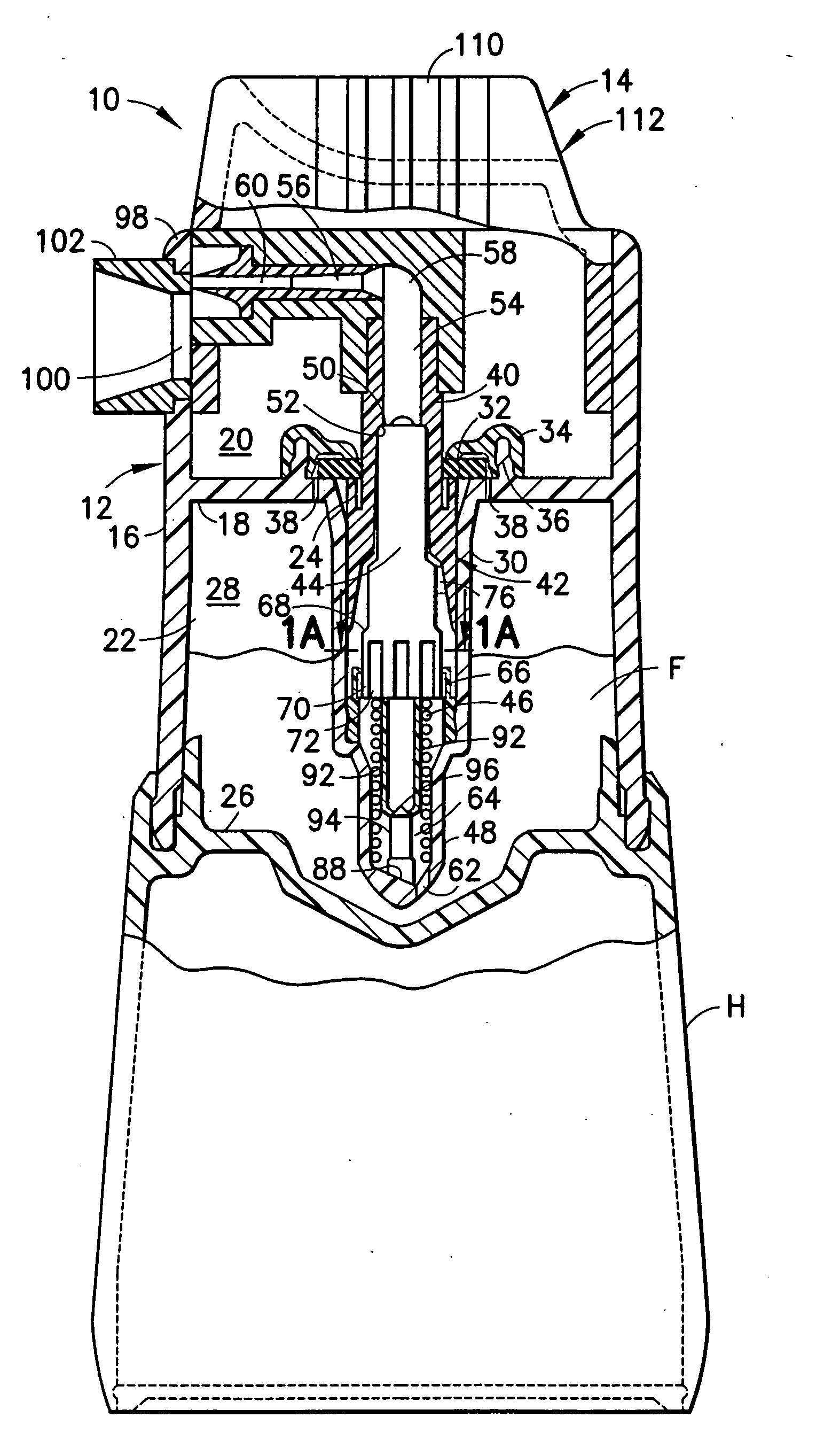
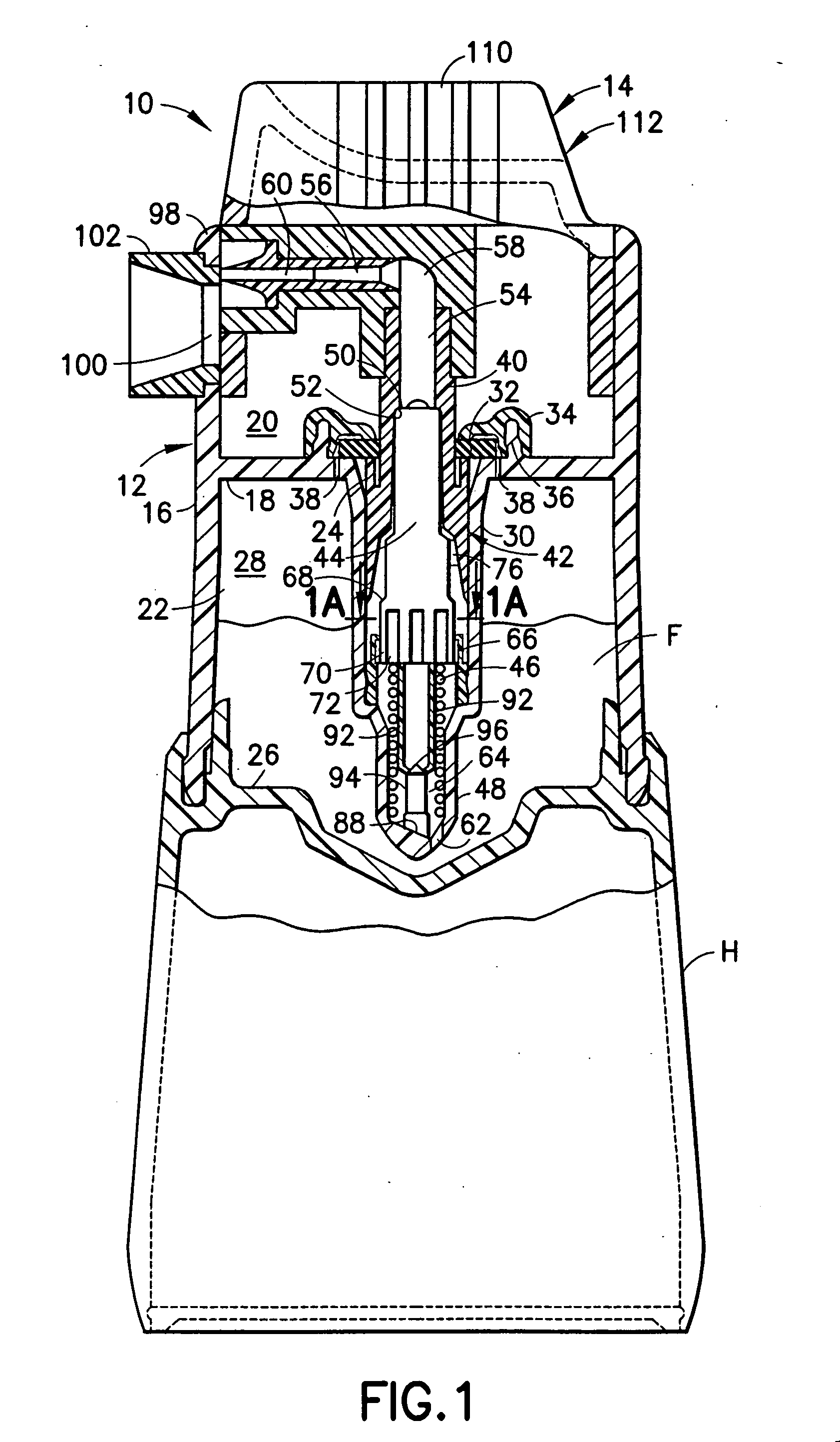
[0026] Referring to the FIGS., a pre-compression pump 10 is shown, along with various features thereof. The pump 10 generally includes a body 12, and a nozzle cap 14.

[0027] The body 12 is formed with a generally tubular outer wall 16 with a transverse web 18 which divides the body 12 into two chambers, an upper chamber 20 and a lower chamber 22, and a web opening 24 communicates the two chambers 20 and 22. The nozzle cap 14 is disposed in the upper chamber 20, whereas, the lower chamber 22 cooperates with a bottom wall 26 to define fluid reservoir 28. The bottom wall 26 may be detachable from the outer wall 16 so as to permit charging of fluid directly into the fluid reservoir 28.

[0028] A tubular cylinder 30 is mounted about the web opening 24 and extends into the fluid reservoir 28. As shown in FIG. 1, a rubber washer 32 is disposed over, and presses against, the cylinder 30. A holding member 34, disposed to engage and hold the rubber washer 32, is preferably snap-fitted onto an ...


PUM


Abstract

A pre-compression pump (10) dispenses microdoses of fluid (F). The pump minimizes pulsing due to pressure fluctuations. The pump is provided with the following to limit pulsing: a low force slow return velocity return spring (46); enlarged fluid passage (58); elastic bumper (74); and, a rachet tooth (76) bearing against the stem (44). Further, a deflectable diaphragm (90), a splined (70) stem (44), no dip tube, and an off-center, gravitational low-point pump inlet (62) assist in printing the pump. The pump includes a stem (44) with deflectable fingers (92) to ensure sufficient momentum in pump operation. Detents (118) and grooves (120) selectively lock a nozzle cap (14) in an inoperative position. To ensure cleanliness, nozzle (60) cleaning is provided, wiping of the nozzle to remove meniscus (M) therefrom, cuts (104) formed in a shroud (98) assist in drawing excess fluid from the nozzle, and an empty volume (108) for collecting fluid run-off from the nozzle. A handle (H) is mounted to the pump providing a grip.

Description

[0001] This application claims priority of U.S. Provisional Patent Application Ser. No. 60 / 150,405, filed Aug. 23, 1999.[0002] This invention relates to pumps for dispensing fluids and medications, and, more particularly, to microdispensing pumps. [0003] In the prior art, positive displacement and pre-compression pumps are known. In addition, U.S. Pat. No. 5,881,956, to the inventors herein, discloses a positive displacement pump which is capable of dispensing microdoses of fluid, as small as 5-10 microliters. U.S. Pat. No. 5,881,956 is incorporated by reference herein. With such small dosing capability, the pumps of U.S. Pat. No. 5,881,956 are advantageously usable to dispense opthalthmic medication. Although some of the teachings of U.S. Pat. No. 5,881,956 can be applied to the pre-compression pump art, there are significant differences between the pumps which prevent full carry-over of the technology. [0004] A pre-compression pump operates on the principle that the pressure build...

Claims


Application Information

Patent Timeline
Patent Type & Authority Applications(United States)
IPC IPC(8): B65D88/54
CPCB05B11/0016B05B11/0032B05B11/0037B05B11/3018B05B11/305B05B11/3052B05B11/3059B05B11/3061B05B15/0208B05B15/52B05B11/0044B05B11/1018B05B11/105B05B11/1061B05B11/1052B05B11/1059
Inventor COHENKELLY, NIGEL
Owner COHEN
Why Eureka
Try Eureka