
Liquid spray unit, method for spraying liquid using it, and chemical

a liquid spraying and liquid technology, applied in the field of liquid spraying units, can solve the problems of product defects, low runability, trouble such as the quality of paper products, etc., and achieve the effect of effectively spraying liquid and high speed of paper making machines or the lik

Inactive Publication Date: 2006-04-27
MAINTECH
View PDF9 Cites 8 Cited by
  • Summary
  • Abstract
  • Description
  • Claims
  • Application Information

AI Technical Summary

Benefits of technology

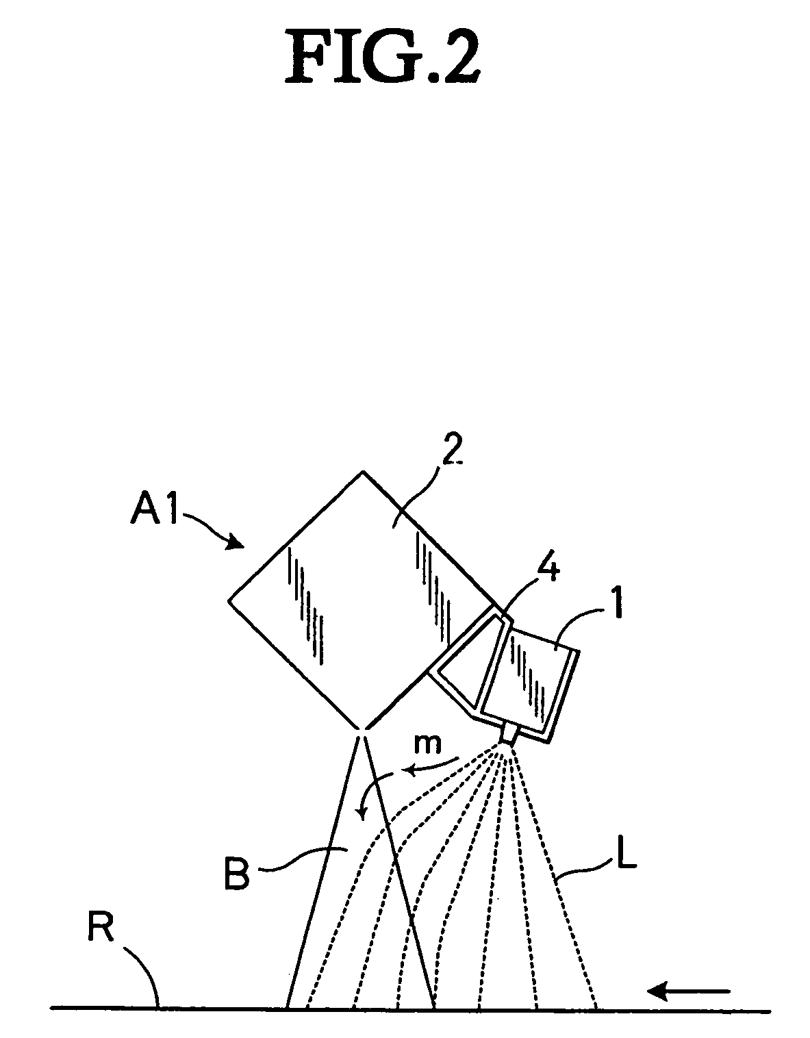
[0049] In accordance with the present invention, it is possible to securely apply the liquid to the traveling body even if the speed of the paper making machine or the like becomes very high, by injecting the air flow from the air flow injecting port to the liquid sprayed from the spray nozzle, and accelerating the liquid so as to spray to the traveling body.
[0050] Further, it is possible to more effectively spray the liquid to the traveling body, by making the unit compact in correspondence to an amount of application of the liquid and space in an inner portion of the paper making machine or the like, and setting the structure to a type of reciprocating a single nozzle.

Problems solved by technology

Accordingly, soils to the members such as the wire, the felt, the drier roll, the canvas and the like increase, as a result, it's caused product defects and low runability.
Further, the rolled-up liquid is attached to a frame, a hood or the like so as to contaminate the paper making machine, and is condensed on a surface of the hood or the like so as to come down on the paper, thereby generating a trouble such as to lower quality of paper products.
Under the extremely strong wind speed and wind pressure of the surface current as mentioned above, the surface current can not be necessarily sufficiently shielded by the air curtain of the unit mentioned above.
When the liquid is sprayed in the state mentioned above, there is a case that a problem that the liquid is rather rolled up violently to the downstream side is generated.
As mentioned above, because of appearance of the paper making machine having very high speed, in the unit employing the technique of shielding the surface current as mentioned above, it becomes hard to achieve the stable spraying of the liquid to the traveling body.

Method used


Image

  • Liquid spray unit, method for spraying liquid using it, and chemical
  • Liquid spray unit, method for spraying liquid using it, and chemical
  • Liquid spray unit, method for spraying liquid using it, and chemical

Examples


first embodiment

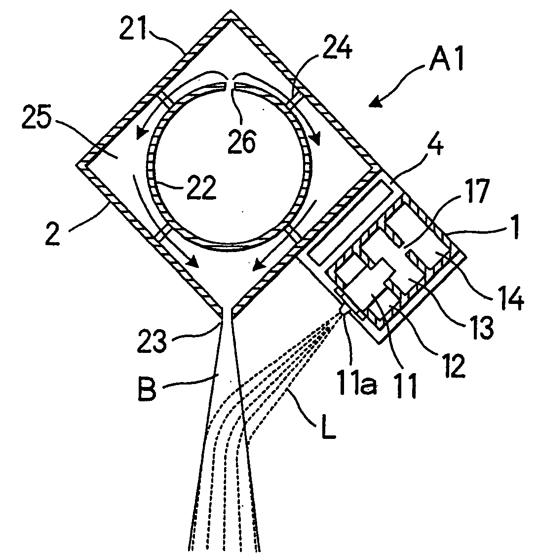
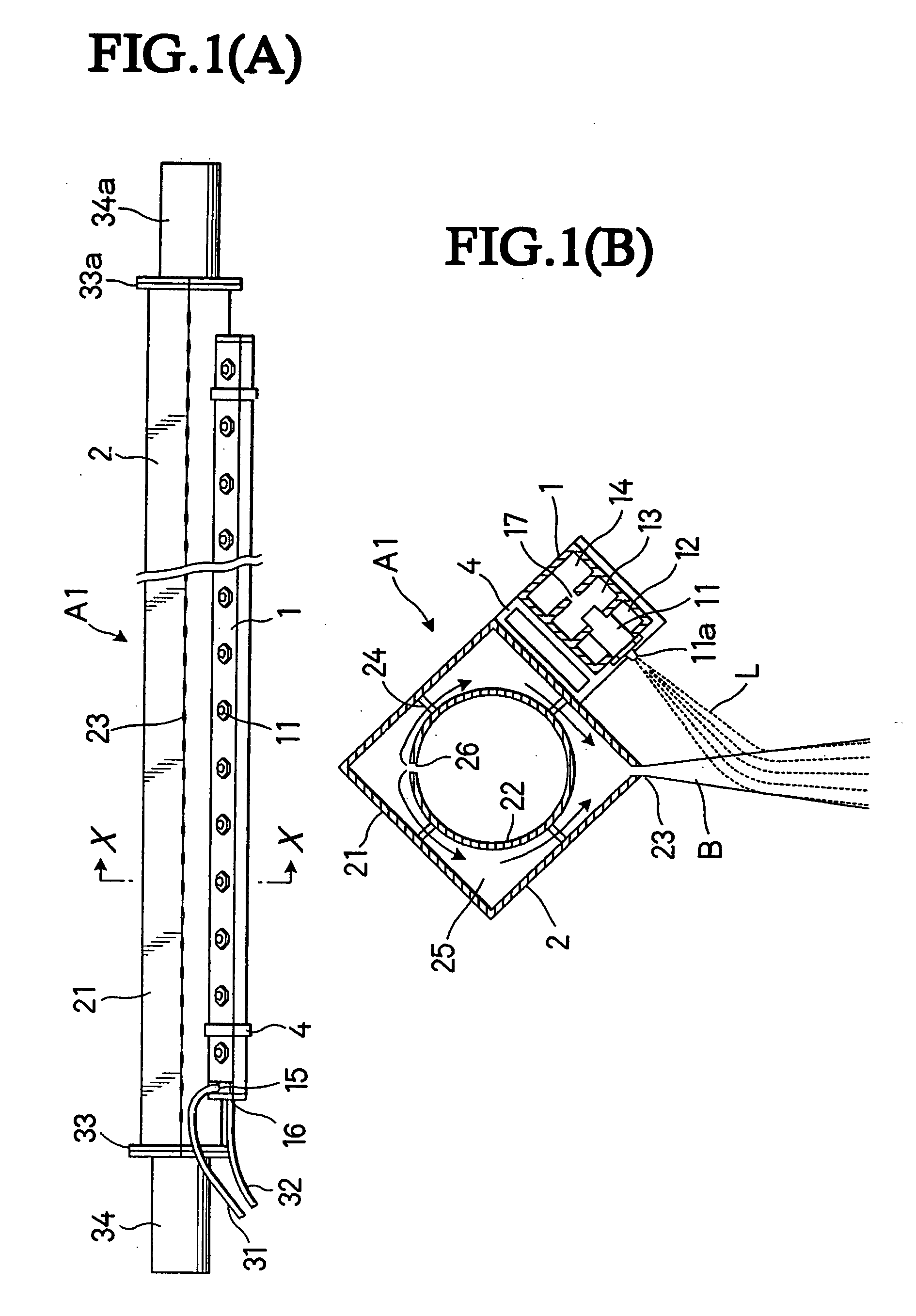
[0064]FIGS. 1A and 1B are views showing an example of structure of a liquid spray unit provided with plurality of spray nozzles in a width direction of a traveling body, in which FIG. 1A is a bottom elevational view and FIG. 1B is a cross sectional view along a line X-X.

[0065] A liquid spray unit A1 of this type is provided with a spray tube 1 and an air box 2.

[0066] The spray tube 1 is provided with plurality of spray nozzles 11 which are arranged in parallel at a fixed interval.

[0067] In the present structural example, since a binary fluid nozzle is used as the spray nozzle 11, the spray tube 1 is provided with a liquid feeding pipe 12 for feeding the liquid to each of the spray nozzles 11, an air feeding tube 13 for feeding compressed air, and a pressure regulating tube 14 for uniformizing pressure of the compressed air inside the air feeding tube.

[0068] In the present structural example, the spray tube 1 is integrally formed such that the liquid feeding tube 12, the air feed...

second embodiment

[0127] As mentioned above, the speed of the paper making machine or the like becomes higher and higher in recent years, however, there is a tendency that the entire unit becomes compact and the interval between the members and the paper becomes narrow.

[0128] Accordingly, there is a case that it is necessary to make the liquid spray unit more compact.

[0129]FIG. 6 is a cross sectional perspective view showing a liquid spray unit which is made more compact.

[0130] The liquid spray unit A2 is formed as compact structure by employing structure obtained by fitting and fixing the spray tube 1 to the air box 2.

[0131] The spray tube 1 has the same structure as the spray tube 1 of the unit A1 mentioned above, and is designed such as to employ the structure used in the unit A1 as it is.

[0132] The air box 2 is provided, in the same manner as the unit A1, an outer wall 21 and an air pipe 22 in an inner portion thereof. The air pipe 22 is fixed to an inner wall of the outer wall 21 via a supp...

third embodiment

[0139] The paper just after being conveyed to the dry part of the paper making machine contains a comparatively large amount of moisture content, and a gum pitch, talc, a micro fiber or the like tends to be transferred from the paper to the drier roll.

[0140] Accordingly, in the case of spraying the antipollution agent, the mold releasing agent or the like containing the wax or the like to the drier roll, if it is sprayed too much, there is a case that the paper is adversely affected inversely.

[0141] As mentioned above, a small amount (micro amount) of liquid spray is frequently requested in the liquid application to the paper making machine or the like.

[0142]FIG. 8 is a perspective view showing a liquid spray unit A3 which is suitable for the small amount of liquid spray mentioned above.

[0143] The liquid spray unit A3 is structured such that the head portion 5 including the spray tube 1 sprays the liquid while reciprocating in the width direction of the traveling body, and spray...


PUM

PropertyMeasurementUnit
Pressureaaaaaaaaaa
Speedaaaaaaaaaa
Widthaaaaaaaaaa

Abstract

A liquid spray unit which can impart liquid (treating liquid, medicine, or the like) surely to a traveling body even in a high speed paper making machine. The liquid spray unit for spraying liquid to a traveling body comprises a spray tube provided with a nozzle for spraying liquid, and an air box provided with an opening for jetting an air flow, wherein the spray tube and the air box are arranged such that the air flow is jetted from the air jet opening toward the liquid sprayed from the spray nozzle and the sprayed liquid can be blown to the traveling body after being accelerated by the air flow. The liquid can be sprayed more effectively to the traveling body by making compact the unit depending on the quantity of liquid being imparted or the inner space of a paper making machine, or the like, or by employing a unit of a type of reciprocating a single nozzle.

Description

TECHNICAL FIELD Technical Field Pertinent to the Invention [0001] The present invention relates to a liquid spray unit applied to an object traveling at high speed, and more particularly, to a liquid spray application unit for securely applying liquid to paper moving at high speed by a paper making machine or the like, kinds of rolls such as a drier roll, a press roll and the like in the paper making machine or the like, and members such as a canvas, wire or the like. BACKGROUND ART Prior Art [0002] In conventional, in order to increase paper strength, make multi-layer paperboard and the like, liquid such as paper strength increasing agent, interlayer adhesive agent or the like is applied to the paper moving inside the paper making machine. [0003] Further, for the purpose of preventing foreign materials caused by pulp raw materials from being transferred from the paper and improving on paper release, the chemical such as antipollution agent, mold releasing agent or the like is appli...

Claims


Application Information

Patent Timeline
IPC IPC(8): B05B7/04B05B7/08B05B7/24D21F1/34D21G7/00D21H21/02D21H21/16D21H21/18D21H21/22D21H23/50
CPCB05B7/08B05B7/0807B05B7/0861B05B7/0884D21F1/34D21G7/00D21H21/02D21H21/16D21H21/18D21H21/22D21H23/50B05B7/02
Inventor SEKIYA, HIROSHI
Owner MAINTECH
Learn More