Driving device, optical apparatus, and image pickup apparatus
- Summary
- Abstract
- Description
- Claims
- Application Information
AI Technical Summary
Benefits of technology
Problems solved by technology
Method used
Image

Examples
first embodiment
[0045] First, a description will be given of the present invention.
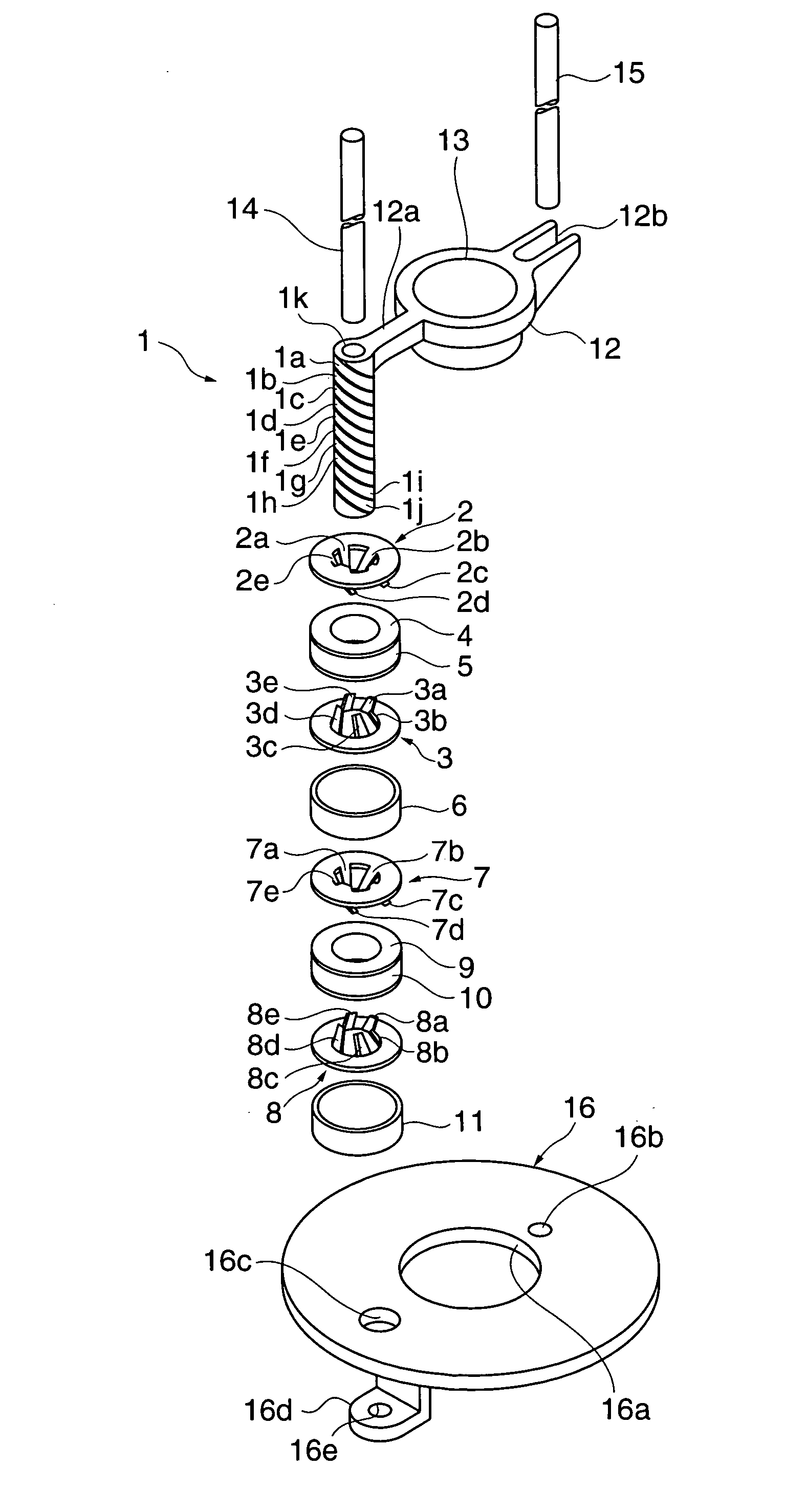
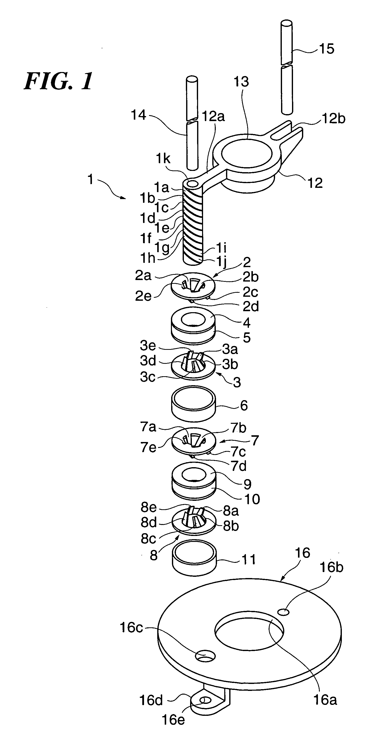
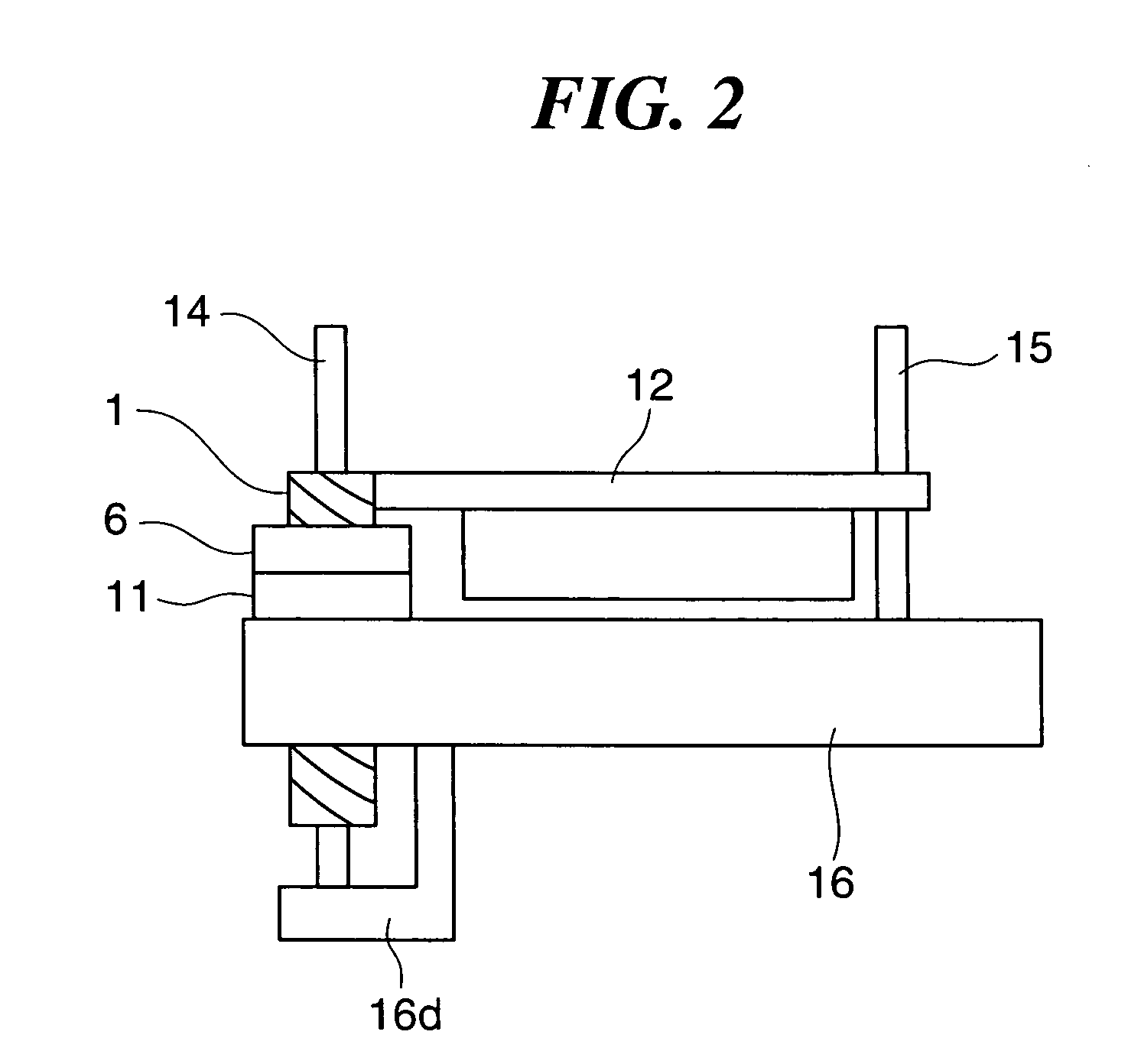
[0046]FIG. 1 is an exploded perspective view of a driving device according to the first embodiment of the present invention. FIG. 2 is a side view of the driving device, FIG. 3 a longitudinal cross-sectional view of essential parts of the driving device, FIG. 4 a cross-sectional view taken on line C-C in FIG. 3, and FIG. 5 a developed plan view showing the relationship between yokes and a magnet. In the following description, it is assumed that the driving device of the present embodiment is used as a driving device for driving a lens of a camera.
[0047] As shown in FIG. 1, the driving device is comprised of a hollow cylindrical magnet 1, a first yoke 2, a second yoke 3, a third yoke 7, and a fourth yoke 8. The magnet 1 has an outer peripheral surface thereof formed with a plurality of magnetized parts 1a, 1b, 1c, 1d, 1e, 1f, 1g, 1h, 1i, and 1j. The magnetized parts 1a to 1j spirally extend along the outer peripheral...
PUM
 Abstract
Description
Claims
Application Information
 - Generate Ideas
- Intellectual Property
- Life Sciences
- Materials
- Tech Scout
- Unparalleled Data Quality
- Higher Quality Content
- 60% Fewer Hallucinations
Browse by: Latest US Patents, China's latest patents, Technical Efficacy Thesaurus, Application Domain, Technology Topic, Popular Technical Reports.
© 2025 PatSnap. All rights reserved.Legal|Privacy policy|Modern Slavery Act Transparency Statement|Sitemap|About US| Contact US: help@patsnap.com