
Vacuum insulation panel and refrigerator incorporating the same

a technology of vacuum insulation panel and refrigerator, which is applied in the field of vacuum insulation panel, can solve the problems of inability to use cases, inability to cure the core of glass wool fiber using a binder, scratching or tear, etc., and achieves the effect of improving reliability, superior heat insulation, and improving reliability of the refrigerator

Inactive Publication Date: 2006-04-27
HITACHI APPLIANCES INC
View PDF5 Cites 32 Cited by
  • Summary
  • Abstract
  • Description
  • Claims
  • Application Information

AI Technical Summary

Benefits of technology

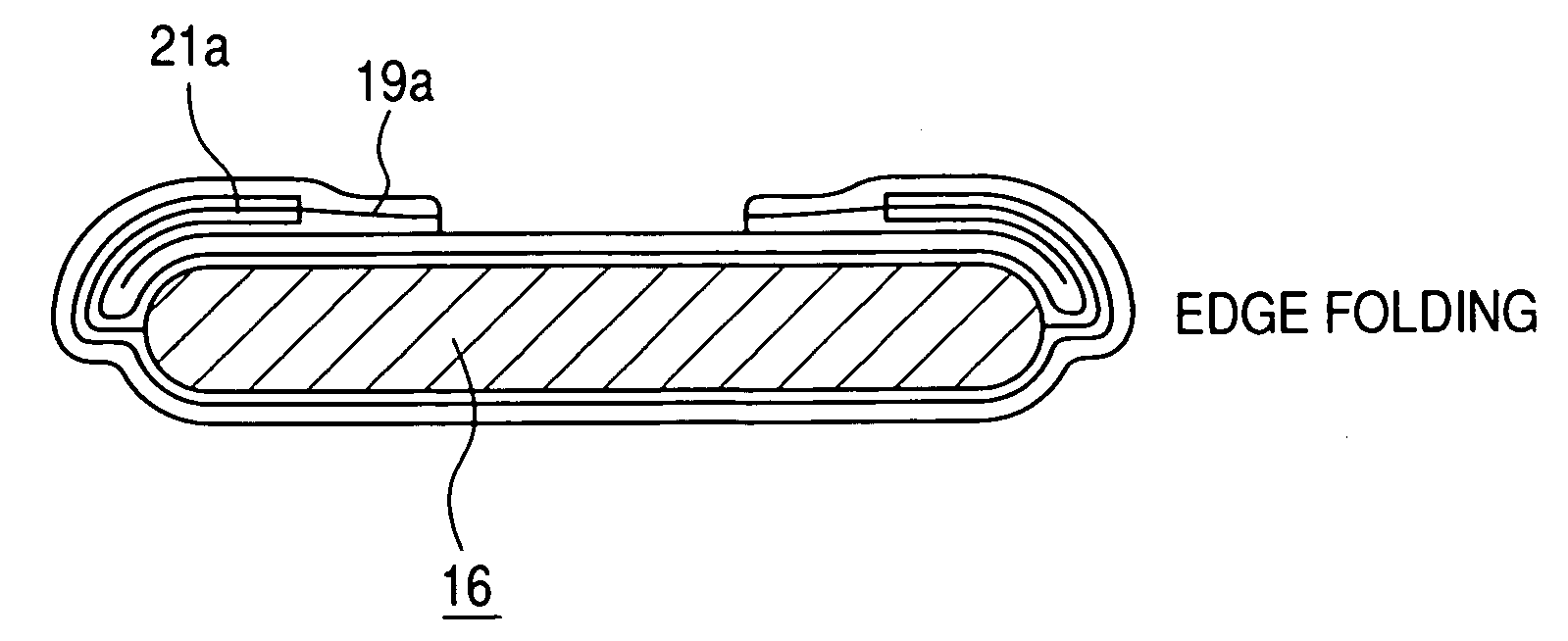
[0024] As described above, edges of the inner film bag containing the inorganic fiber laminate are placed inside edges of the outer barrier bag. Therefore, when an edge of the outer barrier bag is folded back, the radius of bend of the edge is added to by the thickness of the inner film bag. With the edge folded back with a larger radius of bend, even if foreign objects are present in the edge, they are prevented from damaging the outer barrier bag. Furthermore, heat conducted, in the edge portion, from a warmer side of the outer barrier bag via a metallic foil (for example, an aluminum foil layer or an evaporated metallic layer) is partly blocked by the edge of the inner film bag, so that the heat conduction is reduced.
[0043] A vacuum insulation panel according to the present invention has a core produced using no binder, so that it is advantageous in terms of correcting warping and securing flatness accuracy.

Problems solved by technology

Therefore, they cannot be used in cases in which space where insulators can be filled is strictly limited or in cases in which highly effective use of space is imperative.
A core made of such fiber as glass wool cured using a binder, however, may scratch or tear, with burrs formed on it, an outer barrier bag when it is put in the outer barrier bag.
There are however problems associated with placing the vacuum insulation panels toward the inner box.
Therefore, it is difficult to firmly fix vacuum insulation panels to the outer surface of the inner box.
In addition, when foam insulation is filled between the inner box and the outer box, cavities tend to be formed between the vacuum insulation panels and the inner box.
Such cavities if formed may cause the inner box to be deformed and the insulation performance of the refrigerator to decline.
There are however problems posed by the core produced in the above-described way.
For example, when such a core is put in an outer barrier bag or when the interior of an outer barrier bag in which such a core is put is depressurized, burrs formed in end portions of the core when it was cut using a press may scratch or tear the outer barrier bag.
If the core gets deformed in the process of production, it results in a deformed, for example, warped vacuum insulation panel.
Such a vacuum insulation panel may cause trouble when it is attached to the outer box of a refrigerator.
There is another problem with a core produced using a binder.
At such a time, the fiber laminate is powderized into irregularly sized particles which cannot be conveniently recycled.
It is difficult to remove the fiber laminate and the binder separately and re-shape the fiber laminate to produce a new core.
It does not get warped, and convection spaces looking like erected tents are not easily formed between end faces of the core and the outer barrier bag.
In the Japanese Patent Laid-Open No. 4-337195, however, no measure for making convection spaces, which may be formed, smaller is proposed, and no consideration is given to convection spaces which may be formed where an edge of the outer barrier bag is processed.
A problem with such an outer barrier bag is that, with the heat conductivity of aluminum itself being high, heat conduction (heat bridging) via the outer barrier bag makes it difficult to achieve adequate heat insulation performance.

Method used


Image

  • Vacuum insulation panel and refrigerator incorporating the same
  • Vacuum insulation panel and refrigerator incorporating the same
  • Vacuum insulation panel and refrigerator incorporating the same

Examples


Embodiment Construction

[0056] An embodiment of the present invention will be described in the following with reference to FIGS. 1 to 12B.

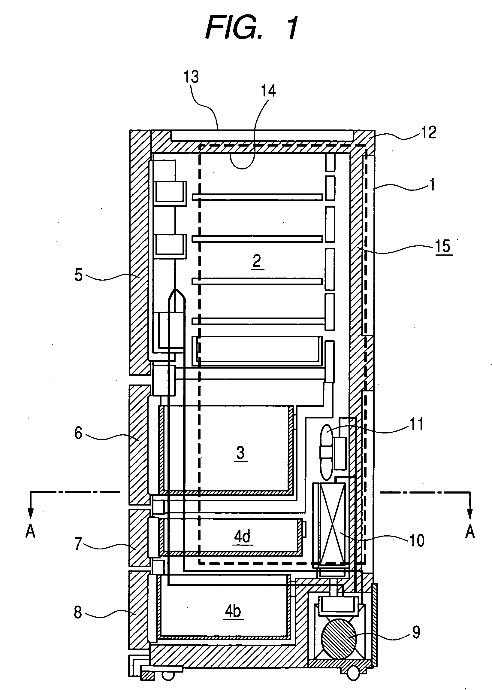
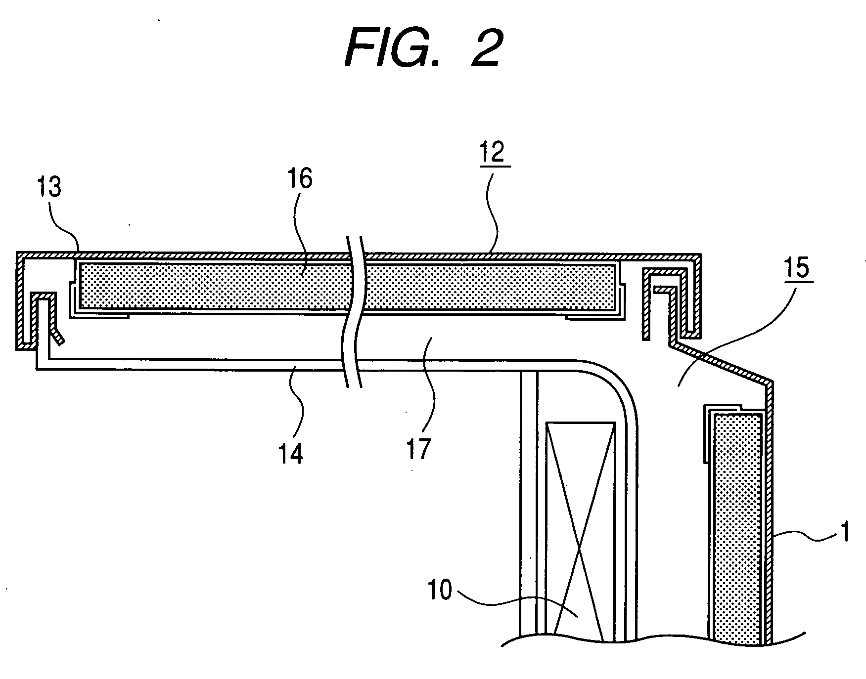
[0057]FIG. 1 is a vertical sectional view of a refrigerator to which the present invention is applied. FIG. 2 is an enlarged view of a principal part taken along line A-A of FIG. 1. FIGS. 3A TO 3C show diagrams for explaining a vacuum insulation panel according to the present embodiment. FIG. 3A shows the vacuum insulation panel according to the present embodiment. Parts (b) and (c) show conventional vacuum insulation panels in general use. FIGS. 4A and 4B show diagrams for explaining a vacuum insulation panel production process according to the present embodiment. FIG. 4A describes a vacuum insulation panel production process according to the present embodiment. FIG. 4B describes a general vacuum insulation production process. FIGS. 5A to 5C show diagrams for explaining a process for producing a core for the vacuum insulation panel according to the present embodiment. ...


PUM

PropertyMeasurementUnit
thicknessaaaaaaaaaa
thicknessaaaaaaaaaa
thicknessaaaaaaaaaa

Abstract

The invention relates to a vacuum insulation panel which can be used as an insulator for a refrigerator requiring heat insulation to be provided and also to a refrigerator incorporating such a vacuum insulation panel. The invention particularly relates to an arrangement for preventing convection spaces from being formed where an edge of the vacuum insulation panel is folded back. The vacuum insulation panel includes a core which has an inner film bag in which a flexible inorganic fiber laminate is accommodated, and an outer barrier bag which is made of gas-impermeable film such as metallic foil laminated film and which accommodates the core. The inner film bag includes a welded portion and a ventilation portion. The outer barrier bag has a depressurized interior and has been sealed by welding. An edge of the inner film bag is placed in an edge of the outer barrier bag.

Description

CLAIM OF PRIORITY [0001] The present application claims priority from Japanese application serial JP 2004-297091 filed on Oct. 12, 2004, the content of which is hereby incorporated by reference into this application. FIELD OF THE INVENTION [0002] The present invention relates to a vacuum insulation panel which can be used as an insulator for a refrigerator requiring heat insulation to be provided and also to a refrigerator incorporating such a vacuum insulation panel. BACKGROUND OF THE INVENTION [0003] In recent years, promotion of energy saving is strongly demanded from a viewpoint of preventing global warming. With regard to electrical home appliances, too, energy saving is an urgent task to be tackled. Particularly, in the field of refrigerators and freezers where efficient use of heat is important, high-performance heat insulators are in high demand. [0004] Insulators made of such fiber as glass wool or such polyfoam as polyurethane foam are in general use. To increase the insul...

Claims


Application Information

Patent Timeline
Patent Type & Authority Applications(United States)
IPC IPC(8): B32B3/02
CPCF16L59/065Y10T428/24248Y10T428/231Y10T428/24215F25D11/00F25D23/00F25D23/06
Inventor ECHIGOYA, WATARUARAKI, KUNINARIKUBOTA, TSUYOSHIMISEKI, TAKASHI
Owner HITACHI APPLIANCES INC
Learn More