Pressure sensor with non-planar membrane

Inactive Publication Date: 2006-05-04
PRECISION MECHATRONICS
View PDF18 Cites 14 Cited by
  • Summary
  • Abstract
  • Description
  • Claims
  • Application Information

AI Technical Summary

Benefits of technology

[0109] Optionally, the wafer bonding is direct wafer bonding wherein the contacting surfaces of the first and second wafers are ultra clean, and activated by making them hydrophilic or hydrophobic prior to bonding, and then brought into contact at high temperature, preferably around 1000° C., Anodic bonding offers another option wherein the contacting surfaces of the first and second wafers have a large voltage applied across them. The wafers may be in a vacuum, air or

Problems solved by technology

Corrugations, a series of raised annuli or other surface features are an added complex

Method used


Image

  • Pressure sensor with non-planar membrane
  • Pressure sensor with non-planar membrane
  • Pressure sensor with non-planar membrane

Examples


Embodiment Construction

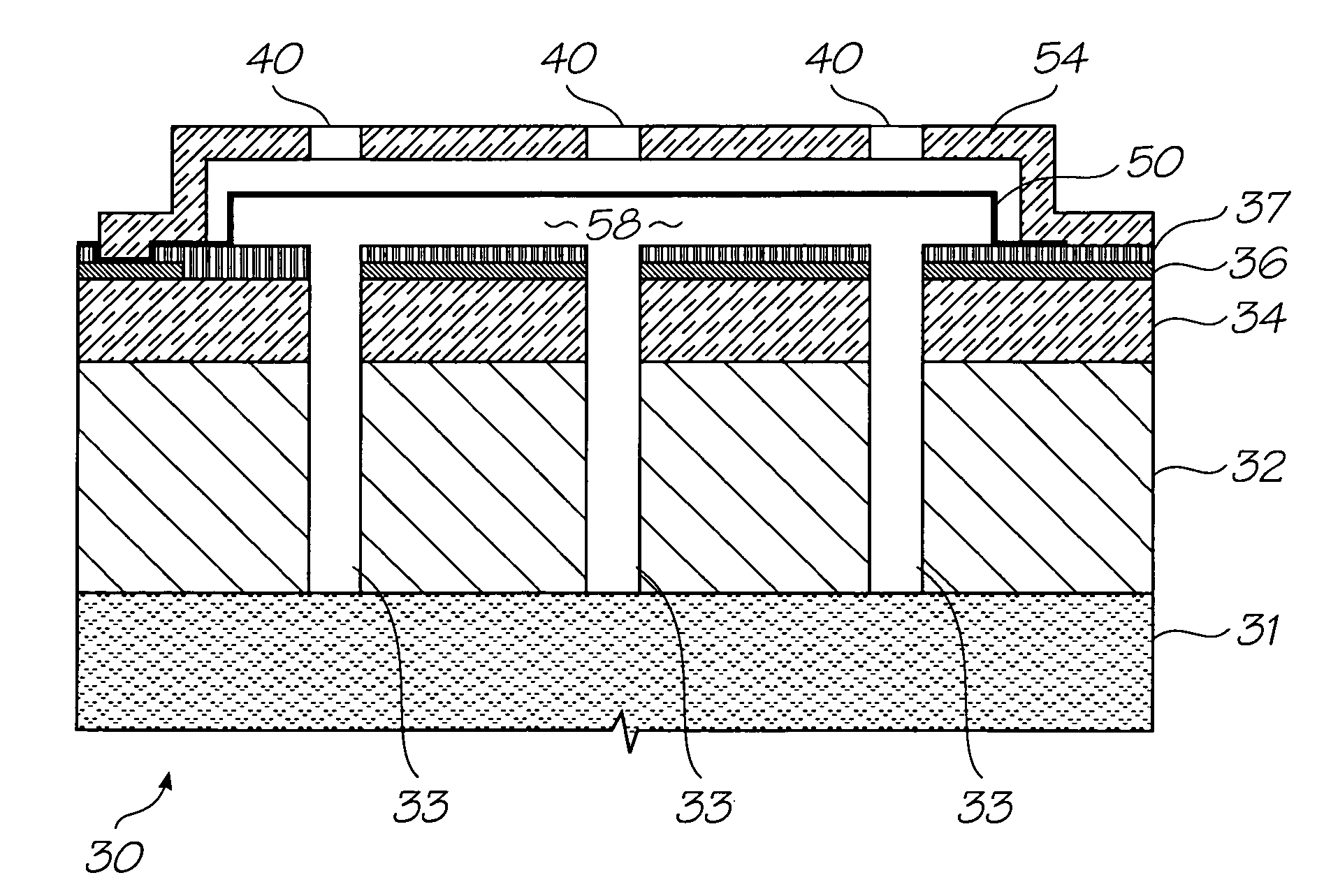
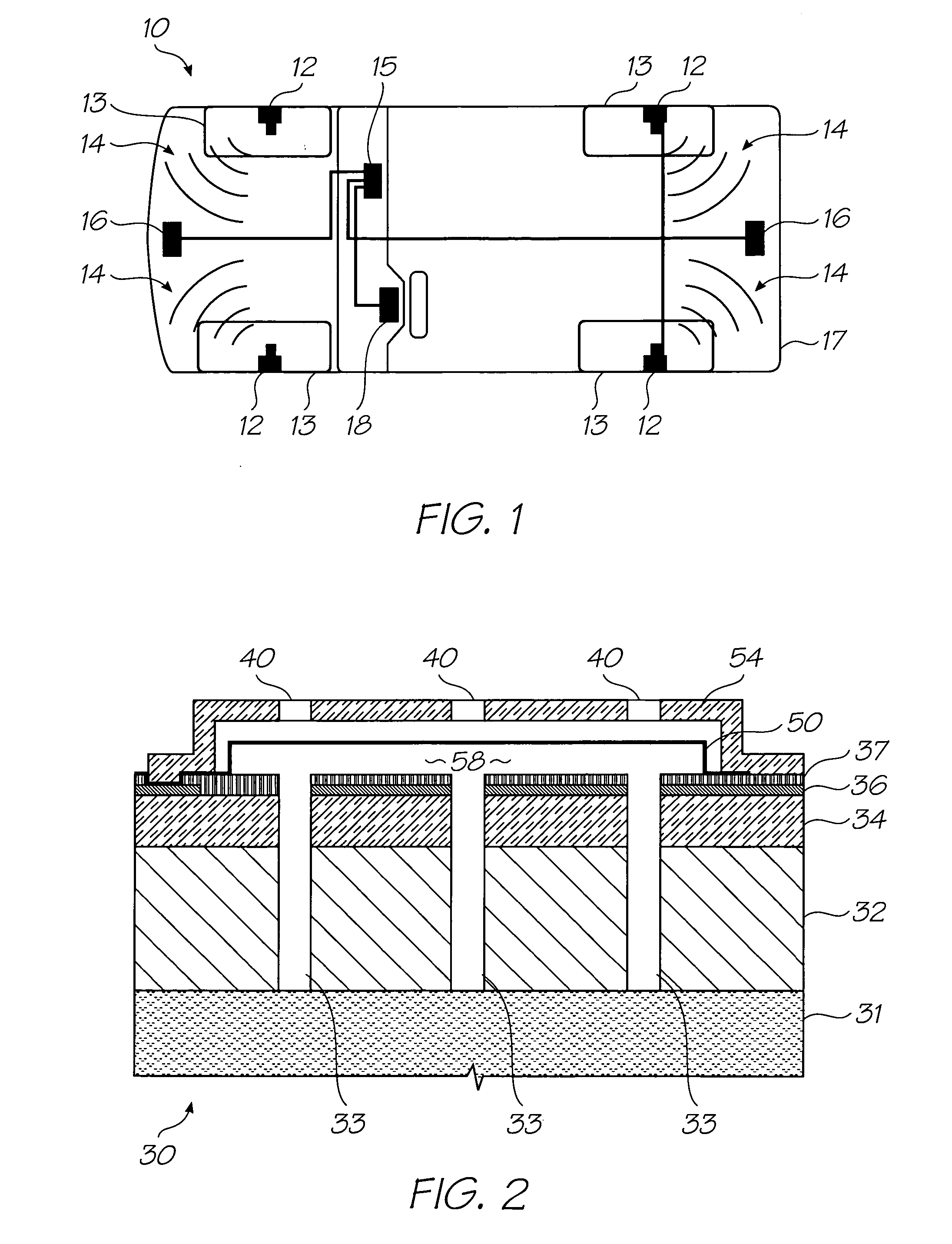
[0126] The following embodiments are described in order to provide a more precise understanding of the subject matter of the present invention. While the embodiments focus on a capacitative type sensor, ordinary workers in this field will readily understand that the invention is equally applicable to other forms of pressure sensor such as: [0127] (i) Piezo-resistive, where the membrane is formed from a non-conductive material and the piezo material is in contact with the membrane. Deflections of the membrane give rise to piezo-induced changes in resistivity (and hence current, if a voltage is applied) that can be monitored electronically. [0128] (ii) Resonant pressure sensors, where the frequency of oscillation of the membrane depends on the pressure difference. The initial resonance could be activated by using a time-varying electrostatic force between the two electrodes. [0129] (iii) Force compensation pressure sensors, where an electrostatic force is applied to maintain the membr...


PUM


Abstract

A pressure sensor for sensing a fluid pressure in harsh environments such as the air pressure in a tire, by using a chamber partially defined by a flexible membrane (20), the chamber containing a fluid at a reference pressure, such that the flexible membrane (20) deflects due to pressure differentials between the reference pressure and the fluid pressure; and,
    • associated circuitry for converting the deflection of the flexible membrane (20) into an output signal indicative of the fluid pressure; wherein,
    • the membrane (20) is non-planar (22, 24).
It is possible to extend the linear range of the pressure-deflection response with a non-planar membrane (20). Corrugations, a series of raised annuli (22) or other surface features are an added complexity in the fabrication process but can extend the linear range of the sensor by 1 MPa.

Description

TECHNICAL FIELD [0001] The present invention generally relates to a pressure sensor and in particular, a micro-electro mechanical (MEMS) pressure sensor. CO-PENDING APPLICATIONS [0002] Various methods, systems and apparatus relating to the present invention are disclosed in the following co-pending applications filed by the applicant or assignee of the present invention simultaneously with the present application: TPS001USTPS002USTPS003USTPS004USTPS005USTPS007USTPS008USTPS009USTPS010USTPS011USTPS012US The disclosures of these co-pending applications are incorporated herein by cross-reference. Each application is temporarily identified by its docket number. This will be replaced by the corresponding USSN when available. CROSS REFERENCES TO RELATED APPLICATIONS [0003] The following patents or patent applications filed by the applicant or assignee of the present invention are hereby incorporated by cross-reference. 09 / 113,07810 / 868,86610 / 043,30010 / 043,29910 / 129,50210 / 043,35010 / 129,50...

Claims


Application Information

Patent Timeline
IPC IPC(8): G01L9/00
CPCB60C23/0408G01L9/0047G01L9/125G01L15/00G01L19/0636G01L9/0073
Inventor SILVERBROOK, KIAMALLINSON, SAMUEL GEORGE
Owner PRECISION MECHATRONICS
Why Eureka
Try Eureka