RFID tag using a surface insensitive antenna structure

a surface-sensitive antenna and rfid technology, applied in the field of radio frequency identification (rfid) tags and labels, can solve the problems of inacceptable variations in the impedance of the rfid device, the dielectric constant, and the variability of the packaging material, and achieve the effect of increasing the thickness of the substra

Active Publication Date: 2006-05-04
AVERY DENNISON CORP
View PDF99 Cites 23 Cited by
  • Summary
  • Abstract
  • Description
  • Claims
  • Application Information

AI Technical Summary

Benefits of technology

[0040] According to another aspect of the invention, a method of forming an RFID device includes: printing one or more layer

Problems solved by technology

A disadvantage of this is that variability of the packaging material, such as its structure and its dielectric constant (the dielectric constant is t

Method used


Image

  • RFID tag using a surface insensitive antenna structure
  • RFID tag using a surface insensitive antenna structure
  • RFID tag using a surface insensitive antenna structure

Examples


Embodiment Construction

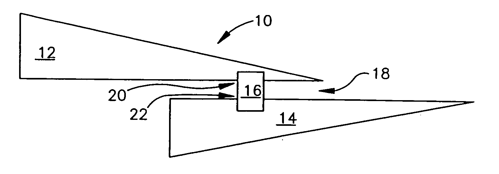
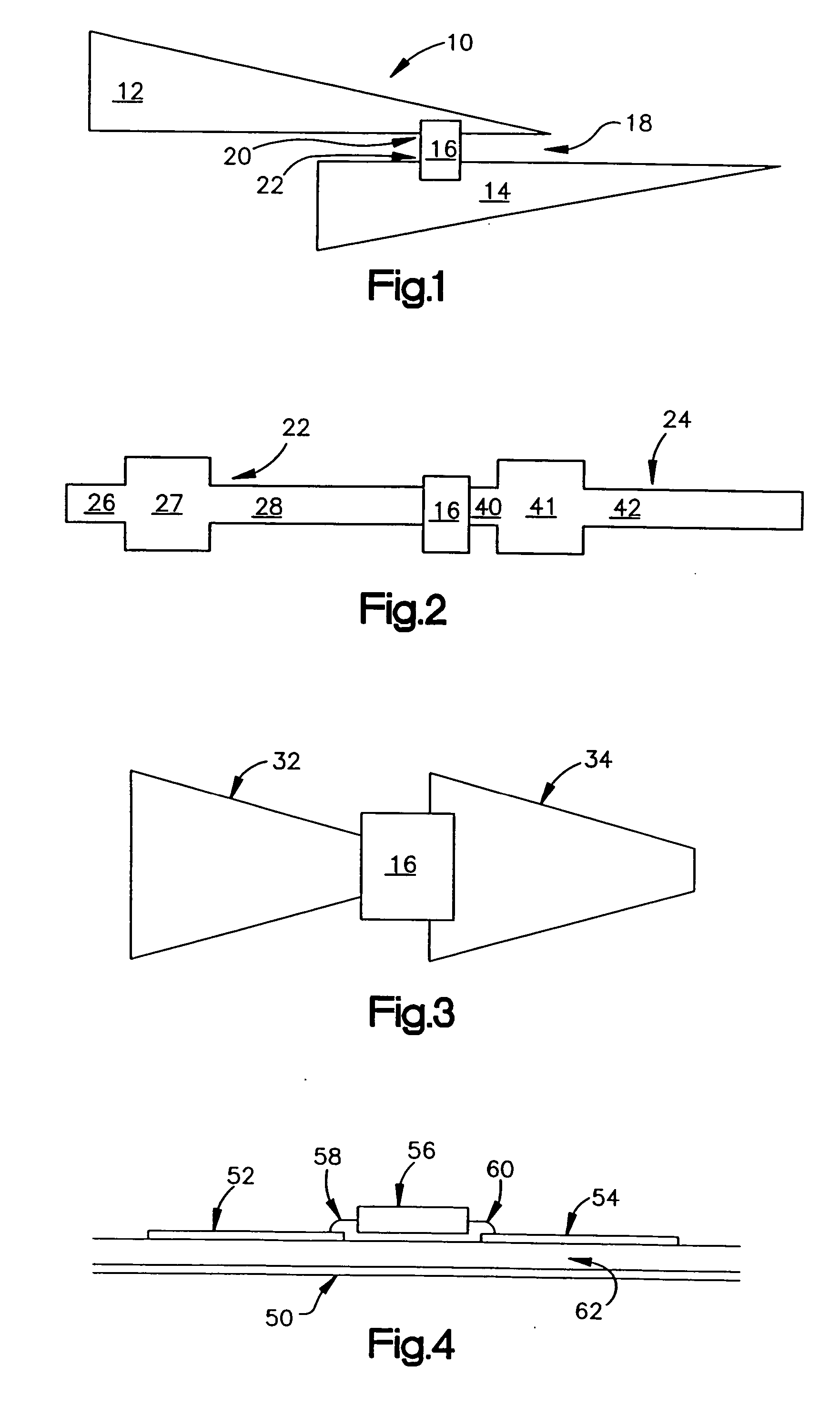
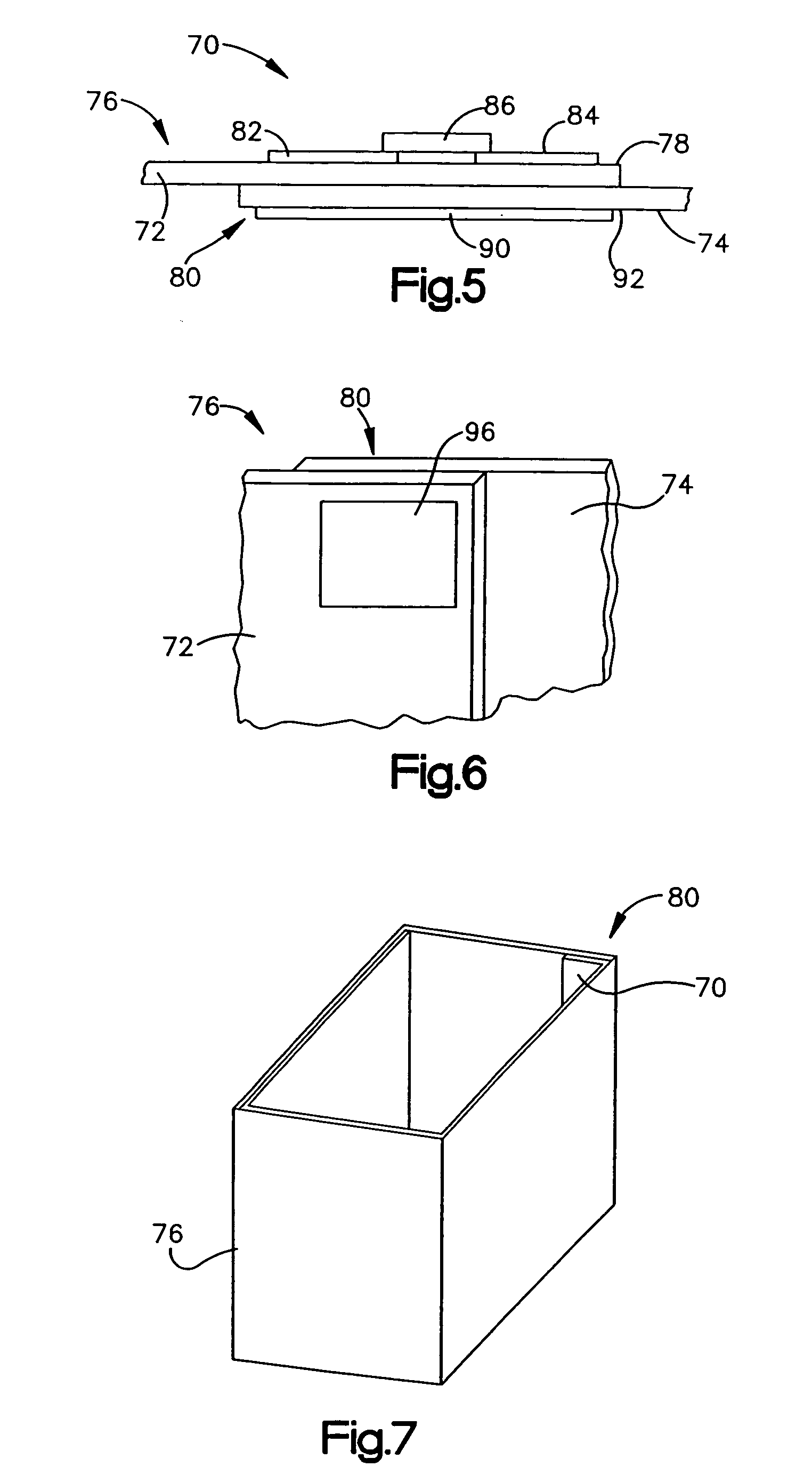
[0059] The present invention is directed to a radio frequency identification device (RFID) and its antenna system as it is attached to a package or container to communicate information about the package or container to an external reader. The package may be an individual package containing specific, known contents, or an individual, exterior package containing within it a group of additional, interior individual packages. The word “package” and “container” are used interchangeably herein to describe a material that houses contents, such as goods or other individual packages, and equivalent structures. The present invention should not be limited to any particular meaning or method when either “package” or “container” is used.

[0060] An RFID device includes conductive tabs, and a conductive structure, with a dielectric layer between the conductive tabs and the conductive structure. The conductive structure overlaps the conductive tabs and acts as a shield, allowing the device to be at...


PUM


Abstract

An RFID device includes conductive tabs, and a conductive structure, with a dielectric layer between the conductive tabs and the conductive structure. The conductive structure overlaps the conductive tabs and acts as a shield, allowing the device to be at least somewhat insensitive to the surface upon which it is mounted, or to the presence of nearby objects, such as goods in a carton or other container that includes the device. The dielectric layer may be a portion of the container, such as an overlapped portion of the container. Alternatively, the dielectric layer may be a separate layer, which may vary in thickness, allowing one of the conductive tabs to be capacitively coupled to the conductive structure. As another alternative, the dielectric layer may be an expandable substrate that may be expanded after fabrication operations, such as printing.

Description

[0001] This is a continuation of International Application No. PCT / US04 / 11218, filed Apr. 12, 2004, published in English as WO 2004 / 093246. The above application claims priority from U.S. Provisional Application No. 60 / 517,156, filed Nov. 4, 2003, and from U.S. application Ser. No. 10 / 410,252, filed Apr. 10, 2003, now U.S. Pat. No. 6,914,562.BACKGROUND OF THE INVENTION [0002] 1. Field of the Invention [0003] This invention relates to the field of Radio Frequency Identification (RFID) tags and labels, and in particular to tags and labels that include a surface insensitive antenna structure. [0004] 2. Description of the Related Art [0005] Current inventory and manufacturing methods rely on the ability to track and identify items of concern, such as inventory items, packages, individual parts, etc., and to communicate information concerning such items of concern in a wireless manner for processing and use. One known method of tracking and providing information on such items of concern ...

Claims


Application Information

Patent Timeline
IPC IPC(8): G06K19/06G08B13/14
CPCG06K19/07718G06K19/07749G06K19/07771
Inventor FORSTER, IAN J.FARR, ADRIAN N.HOWARD, NORMAN A.HOLMAN, ANDREW W.
Owner AVERY DENNISON CORP
Why Eureka
Try Eureka