Imaging rotation angle absolute encoder

a technology of absolute encoder and rotation angle, which is applied in the field of measuring devices, can solve the problems of increasing the cost, complexity, and physical package size of the encoder, and the disadvantage of being larger than 6′′ in diameter, and achieves the effects of small size, good resolution, and high accuracy

Active Publication Date: 2006-05-04
THE BOEING CO
View PDF10 Cites 20 Cited by
  • Summary
  • Abstract
  • Description
  • Claims
  • Application Information

AI Technical Summary

Benefits of technology

[0011] Using a cylindrical code rod allows absolute encoders to achieve higher accuracies at smaller sizes as compared with code disks. For example, to achieve good resolution (e.g., 0.01″ or 48 nanoradians) with the Renishaw RESR series requires a ring that is about 413 mm in diameter. To achieve the same resolution and much better accuracy with a 12 bit system using the present invention requires a rod that is only 55 mm in diameter. In another example, the MicroE Systems M3500 encoder requires an optical diameter of 4 inches to get to 2 arc seconds. The present invention is believed to be able to achieve more than 10 times better accuracy for only 2 inch diameter for the code rod.
[0012] Furthermore, because the code rod has a much smaller diameter than code disks and a relatively short length, the size of bearings required could also be reduced. This potentially leads to a smaller polar moment of inertia, which is directly proportional to the square of the radius and proportional to the mass. The smaller polar moment would be advantageous to the control side of the design.

Problems solved by technology

To increase accuracy or precision, the number of light passage portions and slits are increased, which also increases the cost, complexity, and physical package size of the encoder.
However, such high precision encoders have the disadvantage of being large in size, e.g. greater than 6″ in diameter.

Method used


Image

  • Imaging rotation angle absolute encoder
  • Imaging rotation angle absolute encoder
  • Imaging rotation angle absolute encoder

Examples


Embodiment Construction

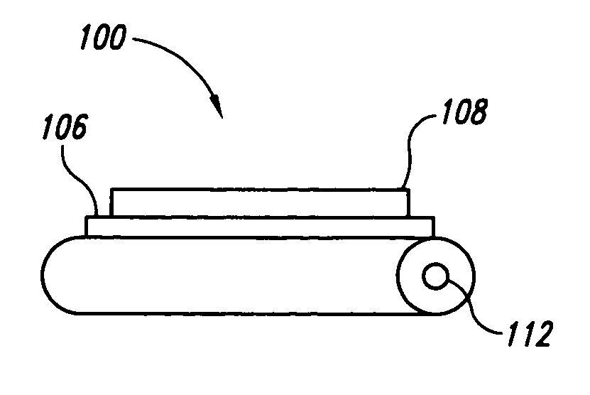
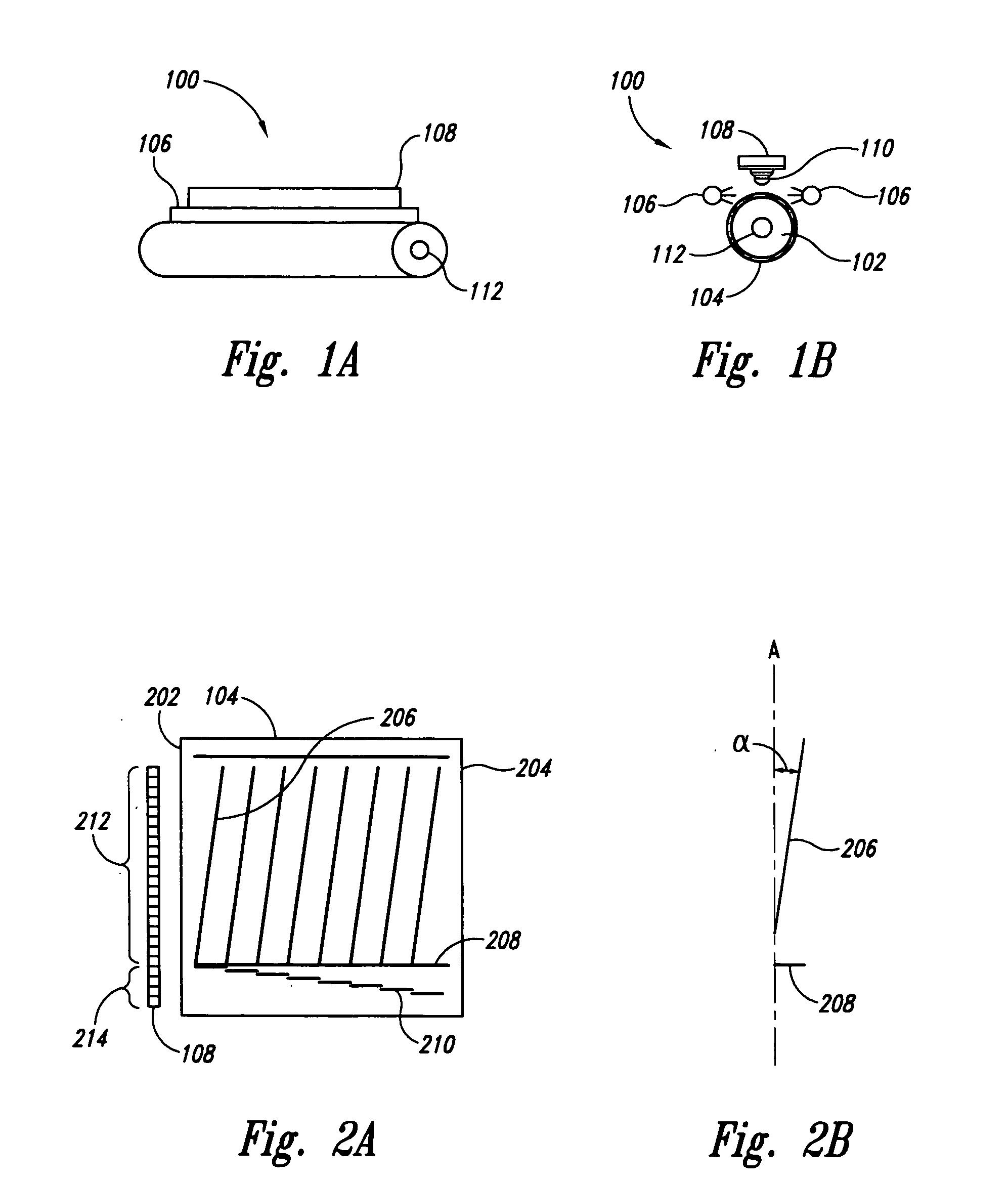
[0021]FIGS. 1A and 1B show side and end views, respectively, of an absolute angle encoder 100 according to one embodiment of the present invention. Encoder 100 includes a cylindrical rod 102 having an encoded surface 104. Light sources 106, such as an array of light emitting diodes, are positioned along the length of rod 102. Light emitted from light sources 106 is reflected from encoded surface 104 and detected by a light detecting linear array 108, such as an array of photodetectors. A cylindrical lens 110 is located between linear array 108 and rod 102. A drive shaft 112 rotates rod 102. As rod 102 rotates, the encoded pattern on encoded surface 104 is illuminated and detected by light array 108 to determine an absolute angular position, as will be discussed in more detail.

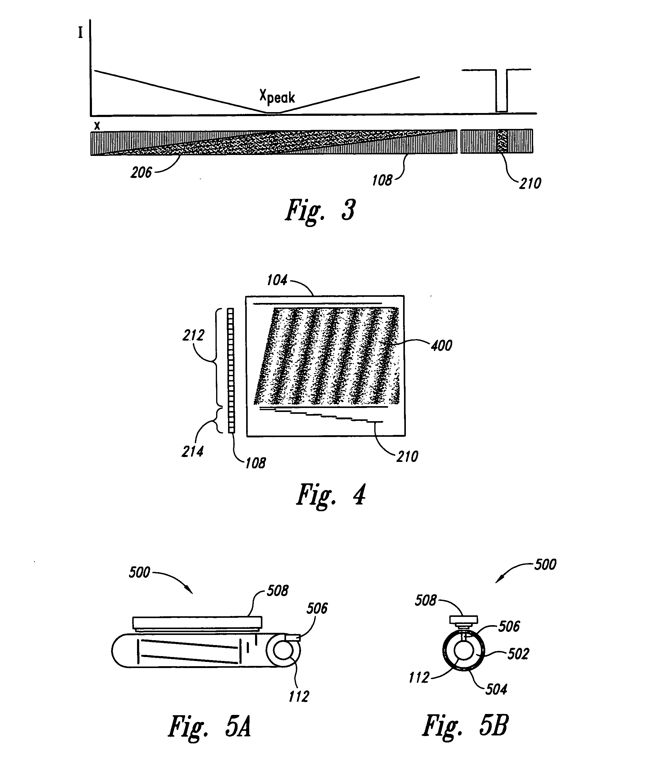
[0022]FIGS. 2A and 2B show one embodiment of encoded surface 104 according to one embodiment. In this embodiment, surface 104 is encoded with a top hat function. FIG. 2A shows surface 104“unrolled” from rod 10...


PUM


Abstract

An angle absolute encoder comprises an encoded code rod that has code marks, such as pairs of fine code lines and coarse code lines. Light is reflected from or transmitted through the code marks and detected by a light detector to determine absolute angle position.

Description

BACKGROUND [0001] 1. Field of the Invention [0002] The present invention relates generally to measuring devices and, more particularly, to absolute encoders for providing position information. [0003] 2. Related Art [0004] Optical encoders are well known and employed for a variety of applications to detect position. An optical encoder measures a position of an object, either angular or linear, by optically detecting marks on a scale attached to the object to move with the object. In the simplest form, the encoder simply measures translation by counting the number of marks that move past the encoder's optical detector. One type of optical encoder is commonly known as an absolute encoder, which has the ability to recognize the position of a movable object without reference to a base, home, or starting position. In a conventional absolute encoder, each position is given by a unique code pattern of marks which identifies the absolute position, as opposed to just one mark. A change in pos...

Claims


Application Information

Patent Timeline
Patent Type & Authority Applications(United States)
IPC IPC(8): G01D5/34
CPCG01D5/34738G01D5/35303
Inventor SAINT CLAIR, JONATHAN M.
Owner THE BOEING CO
Why Eureka
Try Eureka