Linearity corrector using filter products

Inactive Publication Date: 2006-05-04
TEKTRONIX INC
View PDF8 Cites 25 Cited by
  • Summary
  • Abstract
  • Description
  • Claims
  • Application Information

AI Technical Summary

Benefits of technology

[0012] Accordingly, if the distortion mechanisms can be modeled by recovering the coefficients of the equivalent distorting filters in the ADC, the ADC output can be passed through a digital processing network that distorts the signal in substantially the same way, and then subtracts the distortion to reduce, or eliminate, the ADC distortion. Although complete elimination of all the ADC distortion is not possible, this method improves the spurious-free dynamic range (SFDR) of an ADC. For example, an ADC with an SFDR of 80 dB may be improved by a factor of 15 dB, depending upon the ADC characteristics. This improvement also removes some filters from prior proposed topologies, thereby simplifying the design for use with systems that have a relatively flat linear frequency response. This simplification can be traded off for longer filters in the correction system, thereby obtaining improved performance with the same amount of processing. The impro

Problems solved by technology

However, it is typically difficult to remove all sources of errors.
However, some circuit topologies have inherent distortion mechanisms that cannot be completely removed.
This results in some lower level distortions that are hard to eliminate.
Simulating these effects complicates device modeling, and slows computerized simulations.
A filter system with such a large number of taps is too complex and expensive to implement in a practical system at this time.
While it may be a useful subcase of a Volterra filter, it has drawbacks that make it unsuitable for systems with a good linear frequency resp

Method used


Image

  • Linearity corrector using filter products
  • Linearity corrector using filter products
  • Linearity corrector using filter products

Examples


Example

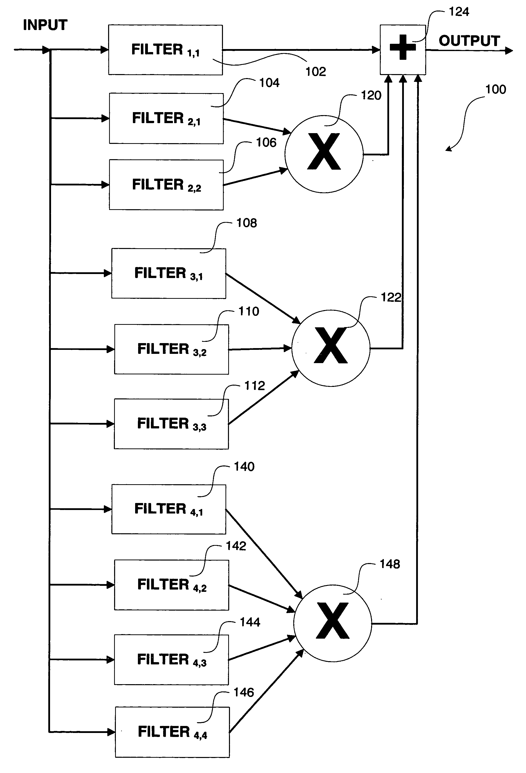
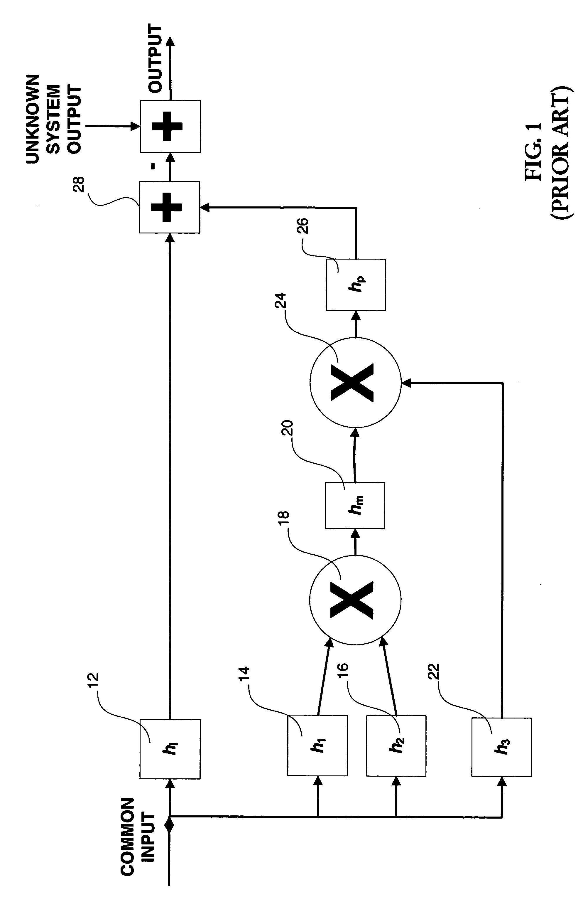
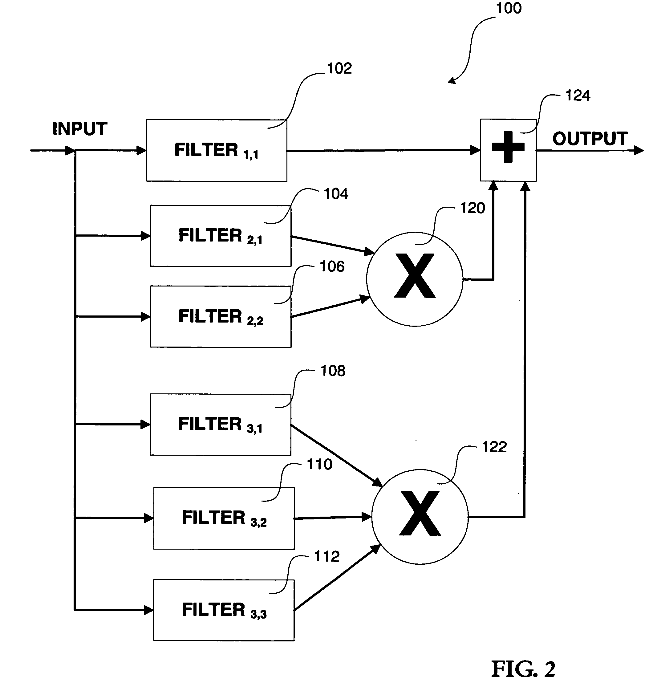
[0020] As was mentioned above, previous proposed solutions have been based on Volterra filters. However, since Volterra filters would be very large and difficult to implement in connection with ADCs, a solution that will utilize a more manageable filter design, while still reducing some of the remaining dominant distortions, would be desirable. Taking the Volterra filter as a starting point, the generalized non-linear filter system can be defined mathematically as: y⁡(t)=h0+∑k=1n⁢(∑j1=0N-1⁢∑j2=0N-1⁢ ⁢…⁢ ⁢∑jk=0N-1⁢hj1,j2, ⁢…⁢ ,jk⁢ ⁢∑i=1k⁢x⁡(t-ji))(Eq. ⁢1)

where N is the impulse response length of the filter, and k is the filter order index.

[0021] For example, if n=3, then we have the sum of a DC value (h0), a linear FIR filter term at k=1, a 2nd-order distortion filter at k=2, and a 3rd-order filter at k=3. Accordingly, for n=3, the Volterra filter can be expressed as: y⁡(t)=h0+∑j1=0N-1⁢hj1⁢x⁡(t-j1)+∑j1=0N-1⁢∑j2=0N-1⁢hj1,j2⁢x⁡(t-j1)⁢ ⁢x⁡(t-j2)+∑j1=0N-1⁢∑j2=0N-1⁢∑j3=0N-1⁢hj1,j2,j3⁢...


PUM


Abstract

A linearity corrector is provided that reduces distortion in a signal processing system, such as an ADC. The linearity corrector provides a first order signal path having distortion components connected to an adder, and a filter product circuit that is also connected to the adder. A method is provided for reducing distortion by calculating a filter product and adding the filter product to a first order signal having a relative delay such that the filter product reduces, or eliminates, the order of distortions corresponding to the order of the filter product.

Description

CROSS-REFERENCE [0001] This application claims the benefit of U.S. provisional application No. 60 / 625,372 filed Nov. 4, 2004.BACKGROUND OF THE INVENTION [0002] The present invention relates to linearity error correction, and more particularly to a linearity corrector using filter products to reduce, or eliminate, distortion generated by signal processing systems, such as an analog to digital converter (ADC). [0003] Reducing distortion produced by ADCs increases the spurious-free dynamic range (SFDR), which is useful for systems that use ADCs to acquire data, such as spectrum analyzers, and other electronic measurement instruments. [0004] Modern high-speed ADC designs use a deep clock pipeline to help accurately convert an analog input to a sampled digital representation in a series of refining steps. The ADC designers make significant efforts to remove obvious sources of nonlinearities in the analog processing circuits. However, it is typically difficult to remove all sources of err...

Claims


Application Information

Patent Timeline
IPC IPC(8): H03M1/06
CPCH03M1/0626H03M1/12
Inventor SLAVIN, KEITH R.
Owner TEKTRONIX INC
Why Eureka
Try Eureka