Electronic circuit structure, power supply apparatus, power supply system, and electronic apparatus

a technology of electronic circuit and mounting structure, which is applied in the direction of electrical apparatus construction details, high current circuit adaptations, substation/switching arrangement casings, etc., can solve the problems of reducing power efficiency, large output current produces a large amount of heat, and the amount of heat lost in the form of heat is relatively increased, so as to reduce the total resistance of wiring and also the amount of heat generated, and improve the power efficiency to 70% or higher

Inactive Publication Date: 2006-05-04
HITACHI LTD
View PDF13 Cites 22 Cited by
  • Summary
  • Abstract
  • Description
  • Claims
  • Application Information

AI Technical Summary

Benefits of technology

[0023] This invention has an effect of reducing the total resistance of wiring portion and also the amount of heat generated in an electronic circuit mounting structure, a power supply apparatus, an electronic circuit board or in a power supply system. Further, in the power supply apparatus or the power supply system, this invention has an effect of improving the power efficiency to 70% or higher. In the power supply system, this invention can reduce a cooling fan in size and weight or eliminate it, contributing to a reduction in the noise of fan and cost. Furthermore, in an electronic apparatus this invention has an effect of reducing power consumption.

Problems solved by technology

That is, a large output current produces a large amount of heat.
A lower output voltage results in a smaller output power for the same current and the amount of power lost in the form of heat relatively increases, reducing the power efficiency.
With the development of the conventional technology, most of the losses in the power supply apparatus or the power supply system is caused by resistive components.
Further, since the operation voltage of semiconductor devices is decreasing, allowable variations and errors of the power supply voltage is also decreasing.

Method used


Image

  • Electronic circuit structure, power supply apparatus, power supply system, and electronic apparatus
  • Electronic circuit structure, power supply apparatus, power supply system, and electronic apparatus
  • Electronic circuit structure, power supply apparatus, power supply system, and electronic apparatus

Examples


embodiment 1

1. Embodiment 1

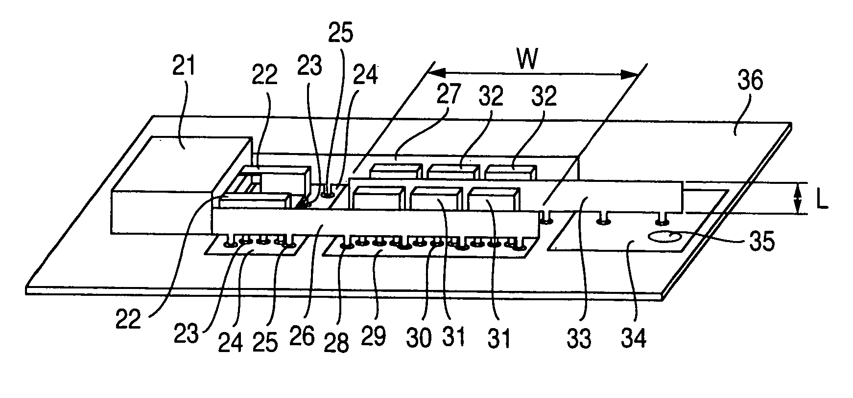
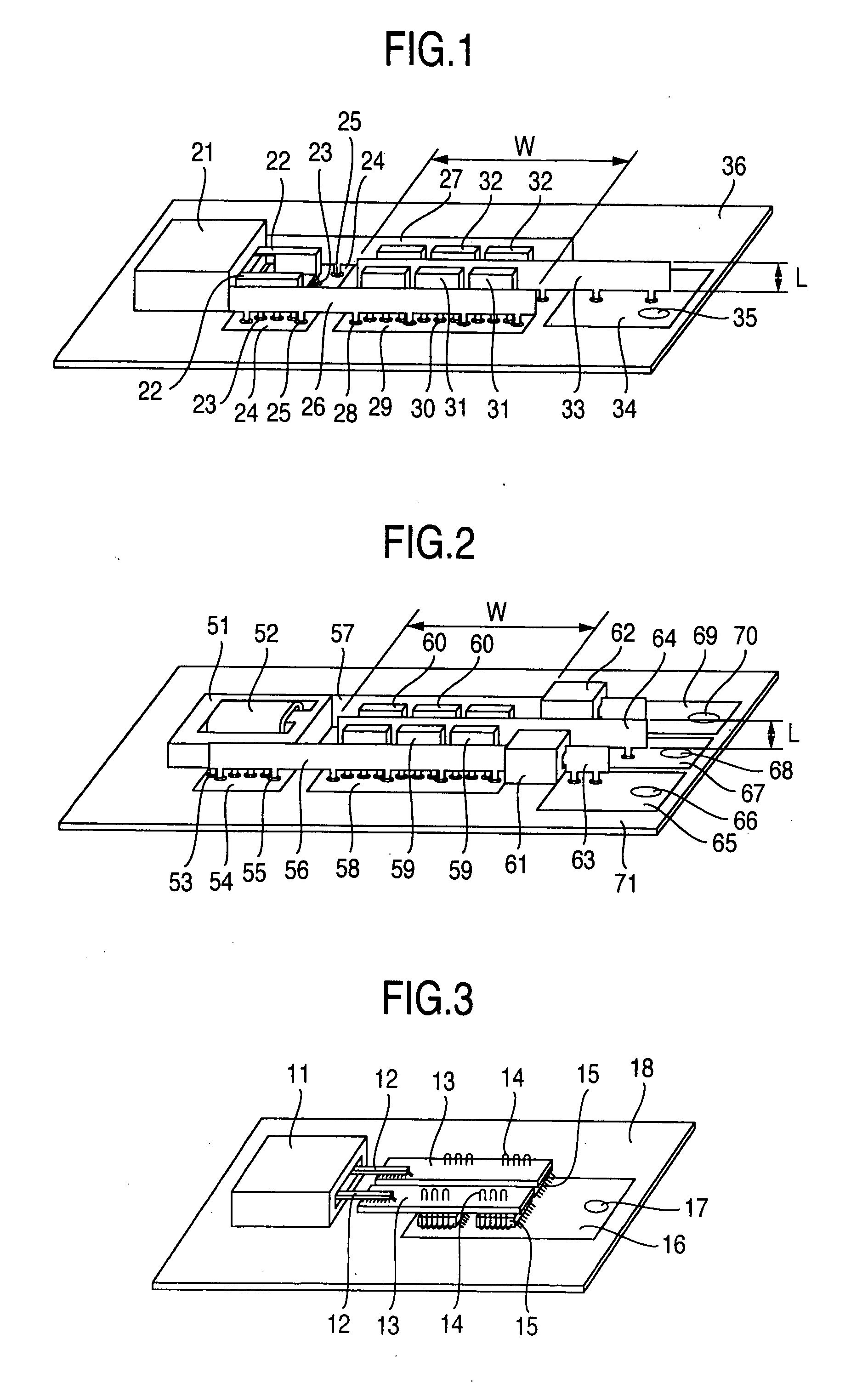
[0040]FIG. 1 shows a mounting structure of an electronic circuit in a first embodiment of this invention and more specifically a mounting structure of a power supply circuit.

[0041] On a printed circuit board 36 are mounted a transformer 21, busbars 26, 27, 33 and semiconductor devices 31, 32. A winding lead 22 of the transformer 21 is shaped like pin terminals and connected to a busbar 26 via a through-hole 23, a wiring pattern 24 and a plurality of through-holes 25. The busbar 26 is shaped like pin terminals and connected to a busbar 33 via a through-hole 28, a wiring pattern 29, a through-hole 30, semiconductor devices 31 and wiring patterns (not shown) in an inner layer of the printed circuit board. The busbar 33 is connected through a wiring pattern 34 to an output terminal 35.

[0042] The similar construction is provided in a path from the transformer 21 to a busbar 27, semiconductor devices 32 and the busbar 33.

[0043] The busbars are metal plates independent of...

embodiment 2

2. Embodiment 2

[0052]FIG. 2 illustrates a second embodiment of this invention of an electronic circuit mounting structure and more specifically a mounting structure of a power supply circuit.

[0053] The second embodiment has a similar structure to the first embodiment but there are also differences, which are described as follows.

[0054] The transformer 51 has one turn of a platelike secondary winding formed integral with a lead portion. The lead portion has a plurality of pin-shaped terminals inserted into through-holes 53 and soldered for connection with a wiring pattern 54 on a printed circuit board 71. A busbar 56 has a magnetic core 61 mounted thereon which functions as an inductance, forming an inductor for a smoothing filter required in a switching power supply circuit. Another busbar 57 also has the similar shape.

[0055] In this second embodiment, a large current path comprises two groups. A first group is made up of a path from the transformer 51 to the busbar 56 to an outp...

embodiment 3

3. Embodiment 3

[0067] A third embodiment of this invention, though not shown, is a power supply printed circuit board made up of busbars, wiring patterns and electronic components. A wiring portion for supplying current to electronic components comprises busbars and wiring patterns, which is similar in construction to the first or second embodiment.

[0068] Since the wiring portion for supplying electricity has the similar construction to the first or second embodiment, the total resistance of wiring is reduced from the conventional 2.6 mΩ to 0.4 mΩ, which is 1 / 6.5 the conventional resistance. As a result, the amount of heat produced is also reduced to 1 / 6.5.

[0069] A voltage drop occurs when a current flows through a resistive wiring. When a current 50 A flows, the conventional wiring of 2.6 mΩ produced a voltage drop of 130 mV, whereas the wiring of this invention with a resistance of 0.4 mΩ has reduced the voltage drop to 1 / 6.5. In this embodiment, the wiring portion for current s...


PUM


Abstract

This invention prevents a deterioration of efficiency of a power supply apparatus due to a semiconductor power supply voltage drop, prevents an increase in wasted power, and prevents erroneous operations due to feeder wire voltage drop. In the mounting structure of electronic circuits having a plurality of busbars as current paths on a printed circuit board, the plurality of busbars have almost parallel portions spaced a predetermined distance apart; a span of the parallel portions of the plurality of busbars is greater than the predetermined distance; and in the parallel portions of the plurality of busbars, the plurality of busbars are connected by a wiring pattern. In the switching power supply apparatus built on a printed circuit board, with its output voltage of less than 2 V and its output current of more than 100 A, a means is provided for making the power efficiency higher than 70%.

Description

INCORPORATION BY REFERENCE [0001] This application claims the priority benefit of Japanese Patent Application No. 2004-314996, filed on Oct. 29, 2004, and No. 2005-013473, filed on Jan. 21, 2005, the entire descriptions of which are incorporated herein by reference. BACKGROUND OF THE INVENTION [0002] The present invention relates to an electronic circuit mounting structure, a power supply apparatus, a power supply system, and an electronic apparatus. [0003] In the power supply apparatus and system, a power efficiency is a very important performance. [0004] The power efficiency is a ratio of an output power to an input power of the power supply apparatus or power supply system, and an electricity that is not used as an output is lost mainly as heat within the system. Thus, if the power efficiency is low, a large amount of heat is produced in the power supply system, which means a large amount of electricity is lost and not used by electronic circuits or load. This in turn requires a ...

Claims


Application Information

Patent Timeline
Patent Type & Authority Applications(United States)
IPC IPC(8): H02B1/20
CPCH05K1/0263H05K2201/10272
Inventor YAMAMURA, HIDEHOMARU, NAOKINAKAJIMA, KAZUNORINISISU, KOJIOOMAE, SHIGEO
Owner HITACHI LTD
Why Eureka
Try Eureka