Monoblock Laser

a laser and monoblock technology, applied in the field of optically, can solve the problems of high cost, bulky, heavy and bulky current fielded laser range finders, and achieve the effects of improving the beam divergence of the laser, increasing brightness, and decreasing the laser beam divergen

Inactive Publication Date: 2006-05-04
UNITED STATES OF AMERICA THE AS REPRESENTED BY THE SEC OF THE ARMY
View PDF6 Cites 9 Cited by
  • Summary
  • Abstract
  • Description
  • Claims
  • Application Information

AI Technical Summary

Benefits of technology

[0008] One object of the present invention is to make monoblock lasers brighter by decreasing the beam divergence of the laser. This is achieved by applying circular apodizing coatings to the various components of the monoblock laser. The apodization of the laser cavity faces improves the beam divergence of the laser and thus, increases brightness, by encouraging only the lower order modes to lase.

Problems solved by technology

Unfortunately, current fielded laser range finders are bulky, heavy and expensive.
Unfortunately, the beam divergence of the monoblock laser is rather larger (>8 mRad)(low brightness laser) which means a sizable optic is required to collimate the monoblock laser output.

Method used


Image

  • Monoblock Laser
  • Monoblock Laser
  • Monoblock Laser

Examples


Embodiment Construction

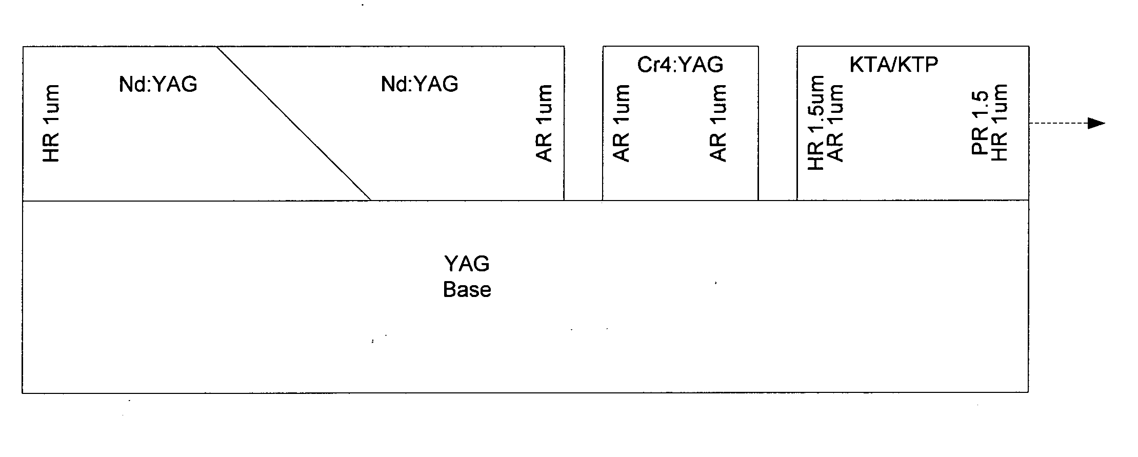
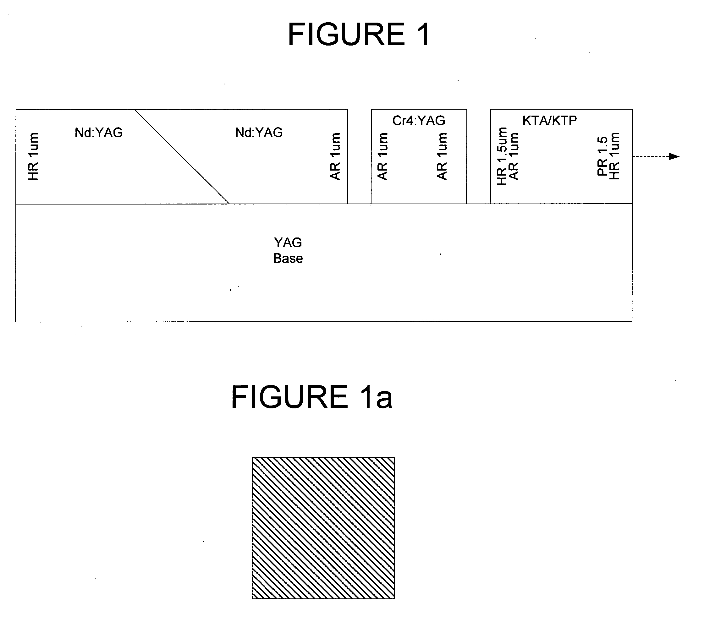
[0012] As shown in FIG. 1, the prior art monoblock laser compromises a block of laser gain material such as Neodymium:Yttrium-Aluminum-Garnet (Nd:YAG) and a high reflector having a wavelength about 1 um disposed on one side and an antireflector having a wavelength of 1 um disposed on an opposite end. Optically coupled to the laser gain material is a Q-switch made of a material such as Cr4+:YAG. The Q-switch is coupled to the laser gain material with an antireflector coating matching (1 um) the antireflector coated on the laser gain material. The Q-switch at the opposite end has another an antireflector coating of 1 um disposed at an output end of the Q-switch. Then, the Q-switch is optically coupled to the OPO cavity which has, in order, a high reflector coating of 1.5 um, an antireflector coating of 1 um on an input end and then, at the output end, a partial reflector coating of 1.5 and a high reflector coating of 1 um. The OPO cavity may be made of such materials as KTiOPO4 (KTP) / ...


PUM


Abstract

An improved monoblock laser cavity is made by applying circular apodizing coatings to the various components of the monoblock laser. The apodization of the laser cavity faces improves the beam divergence of the laser and thus, increases brightness, by encouraging only the lower order modes to lase.

Description

GOVERNMENT INTEREST [0001] The invention described herein may be manufactured, used, sold, imported, and / or licensed by or for the Government of the United States of America.FIELD OF THE INVENTION [0002] The present invention generally relates to optically pumped, solid-state, Q-switched and linearly polarized laser cavity assemblies and, more specifically, to an improved monoblock laser and the method of making the laser. BACKGROUND OF THE INVENTION [0003] The present invention is an improvement to the monoblock laser described and claimed in U.S. Pat. No. 6,556,614, entitled, Monolithic Solid State LASER Assembly and Method of Manufacture, issued Apr. 29, 2003. This patent is incorporated herein by reference with only the necessary parts being duplicated in this specification. [0004] The invention described in U.S. Pat. No. 6,556,614, is a photon pumped laser cavity assembly consisting of a pair of coaxial rods made from laser gain material with precisely cut side-faces and end-fa...

Claims


Application Information

Patent Timeline
Patent Type & Authority Applications(United States)
IPC IPC(8): H01S3/11H01S3/10
CPCH01S3/02H01S3/0604H01S3/0612H01S3/0621H01S3/0623H01S3/0627H01S3/0804H01S3/08059H01S3/1083H01S3/113
Inventor NETTLETON, JOHN E.
Owner UNITED STATES OF AMERICA THE AS REPRESENTED BY THE SEC OF THE ARMY
Why Eureka
Try Eureka