
Multiaxis focusing mechanism for microarray analysis

a microarray and multi-axis technology, applied in the direction of material analysis, biochemistry apparatus and processes, instruments, etc., can solve the problems of signal acquisition, imaging and analysis problems, deviations such as these, and achieve the effect of reducing target position errors

Inactive Publication Date: 2006-05-04
APPL BIOSYSTEMS INC
View PDF23 Cites 7 Cited by
  • Summary
  • Abstract
  • Description
  • Claims
  • Application Information

AI Technical Summary

Benefits of technology

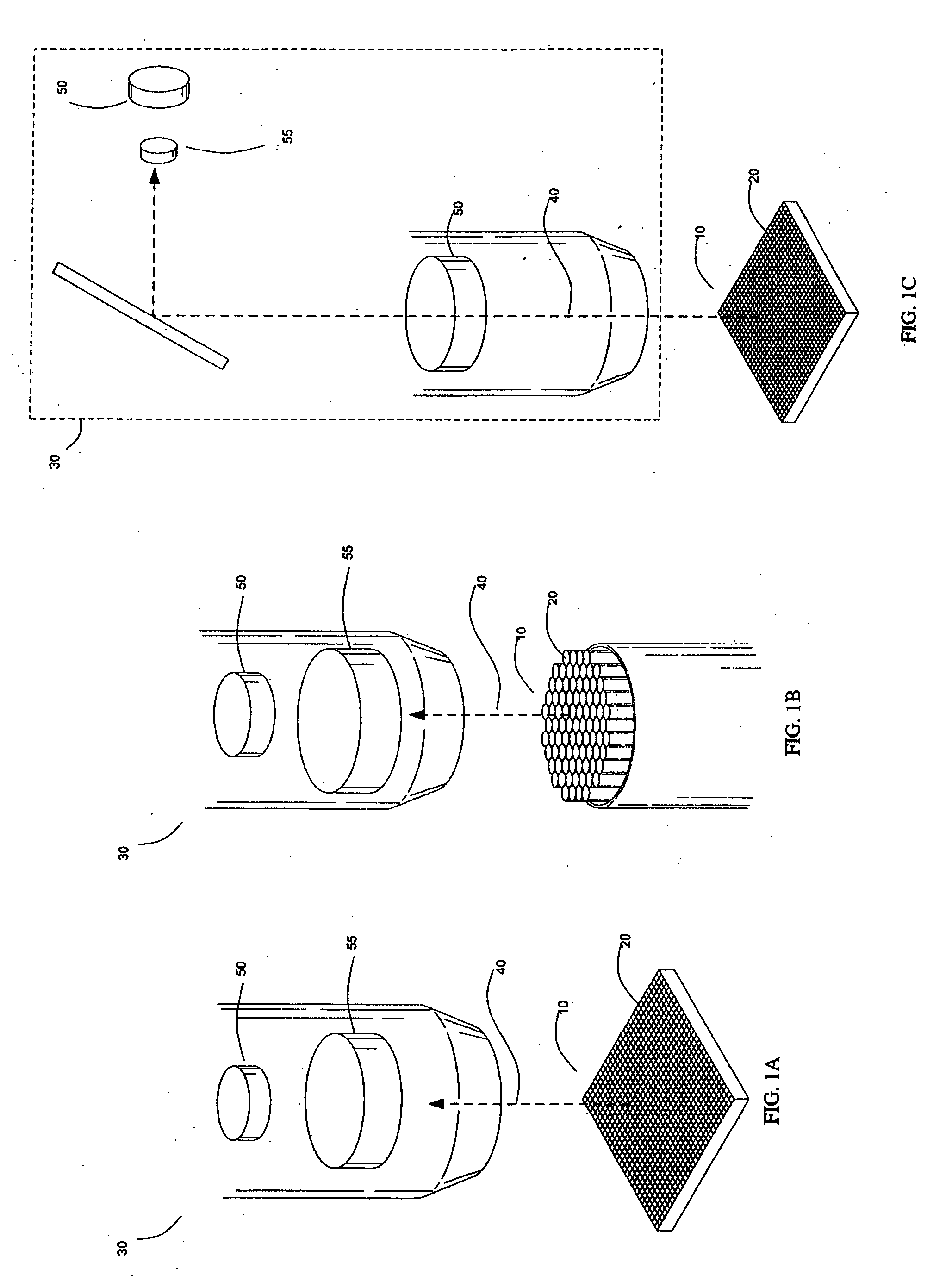
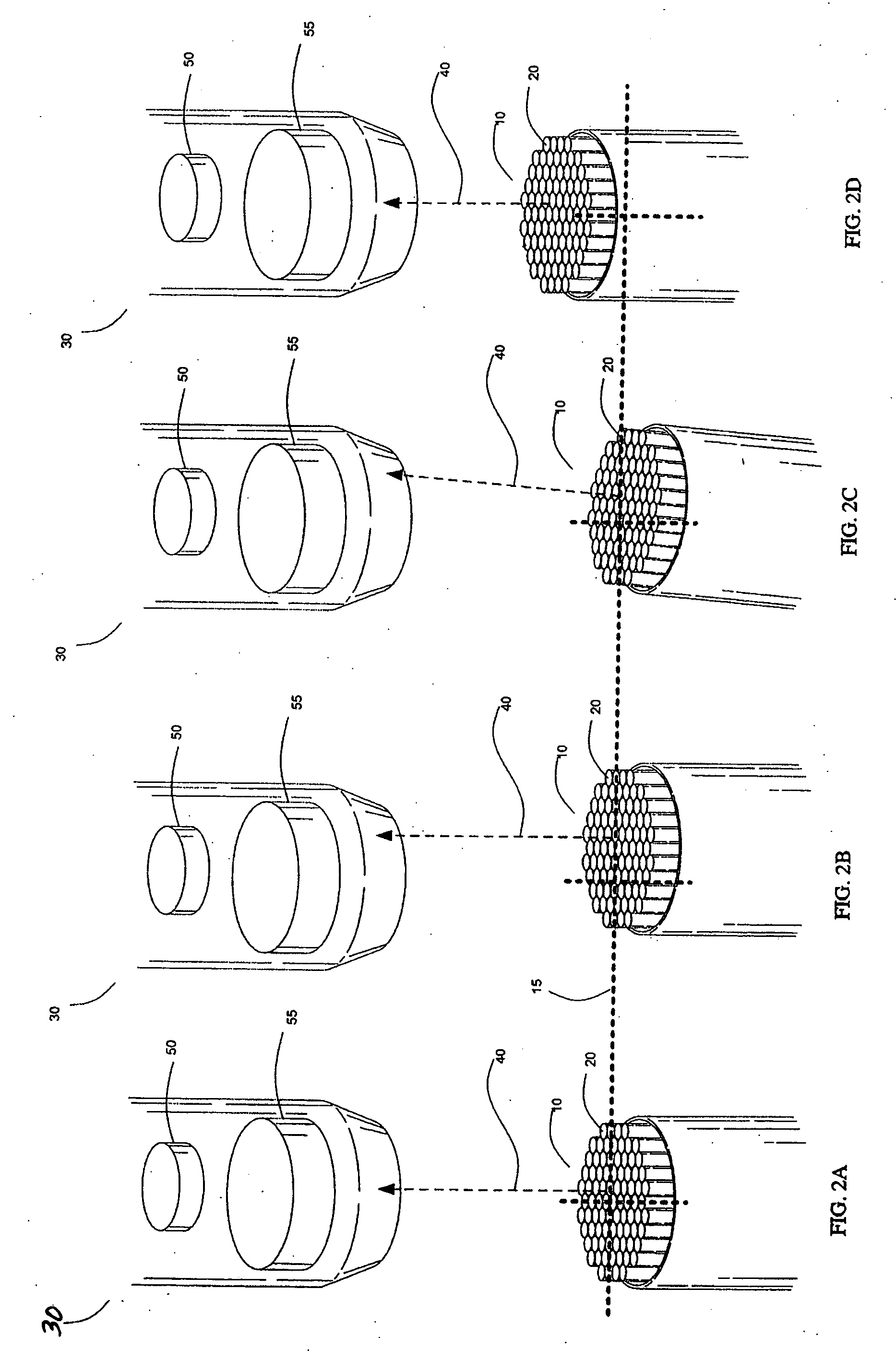
[0003] The present teachings relate to systems and methods for positioning a target relative to a signal acquisition frame. Detection of the target's positional deviation may be achieved through the use of a calibration beam reflected from the target surface and detected by position sensitive detectors (PSDs) thereby allowing removal or correction of focus and / or tilt errors. The PSD-measured quantities associated with these errors can be transformed into quantifiable values and used to reduce and / or compensate for positional errors during signal acquisition. The calibration beam and one or more PSDs may also be used to detect the target's edges or boundaries, thereby allowing centering or positioning of the target relative to the reference frame or signal acquisition device.
[0005] In one embodiment, the positional adjustment mechanism positions the target in such a manner so as to substantially center the target and thereby improve the resolution of signals arising from the features. In one embodiment, the positioning of the target in the selected orientation using the controller improves the resolution of the signals emitted by the features. In one embodiment, the optical axis about which the target is positioned extends substantially perpendicularly to the first reflecting surface.
[0006] In one embodiment, the boundary comprises two substantially parallel sides. The target is positioned laterally along a first direction substantially perpendicular to the two substantially parallel sides to thereby provide a means to determine the positions of the two substantially parallel sides relative to the imaging device which is used to determine the position of the target along the first direction with respect to the imaging device. In one embodiment, the boundary of the first surface defines a polygon having at least two sets of substantially parallel sides such that the position of the target can be determined with respect to the at least two sets of parallel sides to thereby provide a means for determination of the orientation of the target with respect to the imaging device in at least two dimensions. In one embodiment, the boundary of the first surface defines a polygon such that the position of the target can be determined with respect to at least three sets of parallel sides to thereby provide a means for determination of the orientation of the target with respect to the imaging device in at least two dimensions.
[0012] In one implementation, the boundary comprises two substantially parallel sides. The target is aligned laterally along a first direction substantially perpendicular to the two substantially parallel sides to thereby allow determination of the positions of the two substantially parallel sides and provide a means to determine the position of the target along the first direction with respect to the detector. In one implementation, the boundary defines a polygon having at least two sets of substantially parallel sides such that the position of the target can be determined with respect to the at least two sets of parallel sides to thereby provide a means to determine the orientation of the target with respect to the detector in at least two dimensions. In one implementation, the boundary defines a polygon such that the position of the target can be determined with respect to at least three sets of parallel sides to provide a means for determination of the orientation of the target with respect to the detector in at least two dimensions.
[0017] In one embodiment, the target is moved in such a manner so as to substantially center or align the target with respect to the detector thereby improving target signal resolution by the detector. In one embodiment, the target is positioned about an optical axis which extends substantially perpendicularly to the first reflecting surface.
[0019] In one embodiment, the boundary comprises two substantially parallel sides. The target is positioned laterally along a first direction substantially perpendicular to the two substantially parallel sides to thereby allow determination of the positions of the two substantially parallel sides and provide a means to determine the position of the target along the first direction with respect to the detector. In one embodiment, the boundary defines a polygon having at least two sets of substantially parallel sides such that the position of the target can be determined with respect to the at least two sets of parallel sides to thereby provide a means to determine the orientation of the target with respect to the detector in at least two dimensions. In one embodiment, the boundary defines a polygon such that the position of the target can be determined with respect to at least three sets of parallel sides to provide a means for determination of the orientation of the target with respect to the detector in at least two dimensions.

Problems solved by technology

During sample analysis, problems arise when performing signal acquisition due to positional deviations on or beyond the order of the feature size being observed.
In such circumstances, even small positional or reference frame deviations may result in imaging and analysis problems.
Deviations such as these can occur for many reasons, including mechanical tolerance limitations, focusing hysterisis, and other positioning difficulties.

Method used


Image

  • Multiaxis focusing mechanism for microarray analysis
  • Multiaxis focusing mechanism for microarray analysis
  • Multiaxis focusing mechanism for microarray analysis

Examples


Embodiment Construction

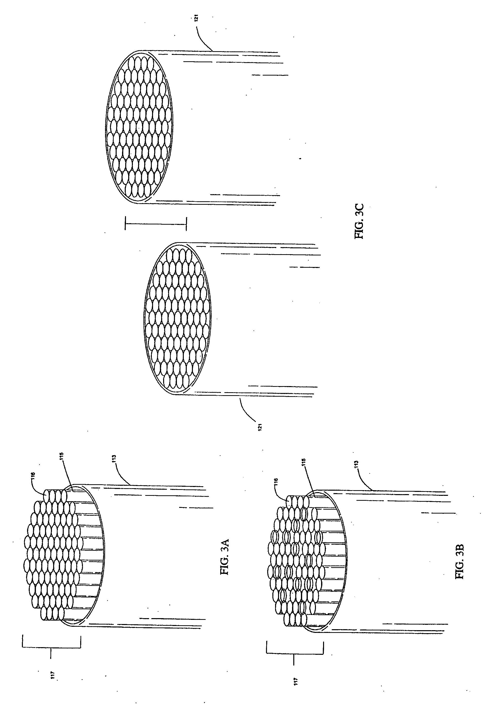
[0046] These and other aspects, advantages, and novel features of the present teachings will become apparent upon reading the following detailed description and upon reference to the accompanying drawings. In the drawings, similar elements have similar reference numerals.

[0047] The system and methods disclosed herein possess a wide range of applicability and, in particular, may be used in conjunction with visible / fluorescent label detection associated with array-based analysis methods and platforms. By way of introduction, array detection technologies encompass a number of different analytical platforms that may be used to detect the presence of one or more target species (e.g. DNA, RNA, proteins, and other biological and non-biological molecules). These technologies have the potential to selectively and simultaneously detect and / or monitor the presence and / or concentration of many hundreds, if not thousands, different molecules or species contained within one or more samples. Addi...


PUM

PropertyMeasurementUnit
diameteraaaaaaaaaa
surface “roughnessaaaaaaaaaa

Abstract

Systems and methods for positioning a multi-featured biological array relative to a signal acquisition device. Detection of the array's positional deviation may be achieved by a calibration beam reflected from the array surface and detected by a position sensitive detector (PSD). The PSD-measured positional deviation can be transformed and used in a control loop to correct for positional variations of the array. The calibration beam and PSD may also be used to detect the array or feature boundaries, thereby allowing lateral centering or positioning of the array relative to the signal acquisition device.

Description

CROSS-REFERENCE TO RELATED APPLICATIONS [0001] This application claims priority to U.S. Provisional Application titled “SYSTEMS AND METHODS FOR DETECTING TARGET FOCUS AND TILT ERRORS DURING GENETIC ANALYSIS,” attorney docket ABIOS.030A, filed Nov. 3, 2003 as U.S. patent application Ser. No. 10 / 700,372 and converted to provisional application on Oct. 1, 2004, U.S. Provisional Application titled “SYSTEMS AND METHODS FOR CENTERING A TARGET DURING GENETIC ANALYSIS,” attorney docket ABIOS.031A, filed Nov. 3, 2003 as U.S. patent application Ser. No. 10 / 700,360 and converted to provisional application on Oct. 1, 2004, and U.S. Provisional Application titled “SYSTEMS AND METHODS FOR CORRECTING TARGET FOCUS AND TILT ERRORS DURING GENETIC ANALYSIS,” attorney docket ABIOS.032A, filed Nov. 3, 2003 as U.S. patent application Ser. No. 10 / 700,362 and converted to provisional application on Oct. 1, 2004, which are incorporated herein by reference.FIELD [0002] Biochemical analysis using arrays repre...

Claims


Application Information

Patent Timeline
Patent Type & Authority Applications(United States)
IPC IPC(8): C12Q1/68G06F19/00G06K9/00G06V10/24
CPCG06K9/00127G06K9/32G06V20/69G06V10/24
Inventor WARREN, SCOTT R.HOFF, LOUIS B.OLDHAM, MARK F.
Owner APPL BIOSYSTEMS INC
Learn More