Closed-loop signalling method for controlling multiple transmit beams and correspondingly adapted transceiver devices

Active Publication Date: 2006-05-04
NOKIA TECHNOLOGLES OY
View PDF13 Cites 115 Cited by
  • Summary
  • Abstract
  • Description
  • Claims
  • Application Information

AI Technical Summary

Benefits of technology

[0080] The constraint posed by the subspace structure also allows to provide feedback in a lower dimensional space (as if the transmitter had fewer antenna elements for each of the less dominant beams). Stated in other words, with reference to a matrix representation of feedback information, some (conventionally present) information is not present, thus “removed” or “suppressed” according to embodiments of the present invention. When only a few bits are used to represent (the coordinates of) less dominant beams, they are in general not orthogonal to other beams. When this happens, the algorithm then naturally orthogonalizes them, and simultaneously changes (typically reduces, but may also be configured to increase) the relative transmit power of the less-dominant beams (power allocation can be also used to achieve this effect). The orthogonalization procedure may prioritize the dominant or most reliable beams, keeping them intact, while modifying the other beams with subspace information.
[0081] In closed-loop transmit diversity (TX diversity): The required number of feedback bits for short term feedback can be reduced as a diversity beam is on the average less powerful than the dominant beam (it can be agreed e.g. that the dedicated diversity beam is transmitted with smaller power and/or with fewer short-term feedback bits).
[0082] In closed-loop MIMO: the required number of feedback bits for short term feedback can be reduced as a beam carrying the additional symbols of a given multi-antenna modulator (for MIMO rate increase) is on the average less powerful than the dominant beam (it can be agreed e.g. that the additional beams are transmitted with lower data or symbol rate).
[0083] According to practical research work of the inventor, MIMO simulations were carried out, where two instantaneous beams are fed back to a Node_B and/or Base Transceiver Station BTS, and two parallel 16QAM (quadrature amplitude modulation) streams are transmi

Problems solved by technology

However, in conventional FDD systems (Frequency Divisional Duplex) channel reciprocity does not hold, and a feedback channel conveying channel-related information from the receiver to the transmitter is needed to thereby perform a feedback control of the diversity transmission.
Also, since a second transceiver, mostly for practical purposes, has a limited diversity capability as compared to the first transceiver (e.g. due to a limited space for plural antenna elements and due to cost reasons involved in designing the UE's/MS's representing in the chosen downlink example the second transceiver) the feedback

Method used


Image

  • Closed-loop signalling method for controlling multiple transmit beams and correspondingly adapted transceiver devices
  • Closed-loop signalling method for controlling multiple transmit beams and correspondingly adapted transceiver devices
  • Closed-loop signalling method for controlling multiple transmit beams and correspondingly adapted transceiver devices

Examples


Example

[0127] A first specific embodiment will be described in the following with reference to FIG. 4. FIG. 4 illustrates the entire scenario while going into details of FIGS. 2 and 3, respectively.

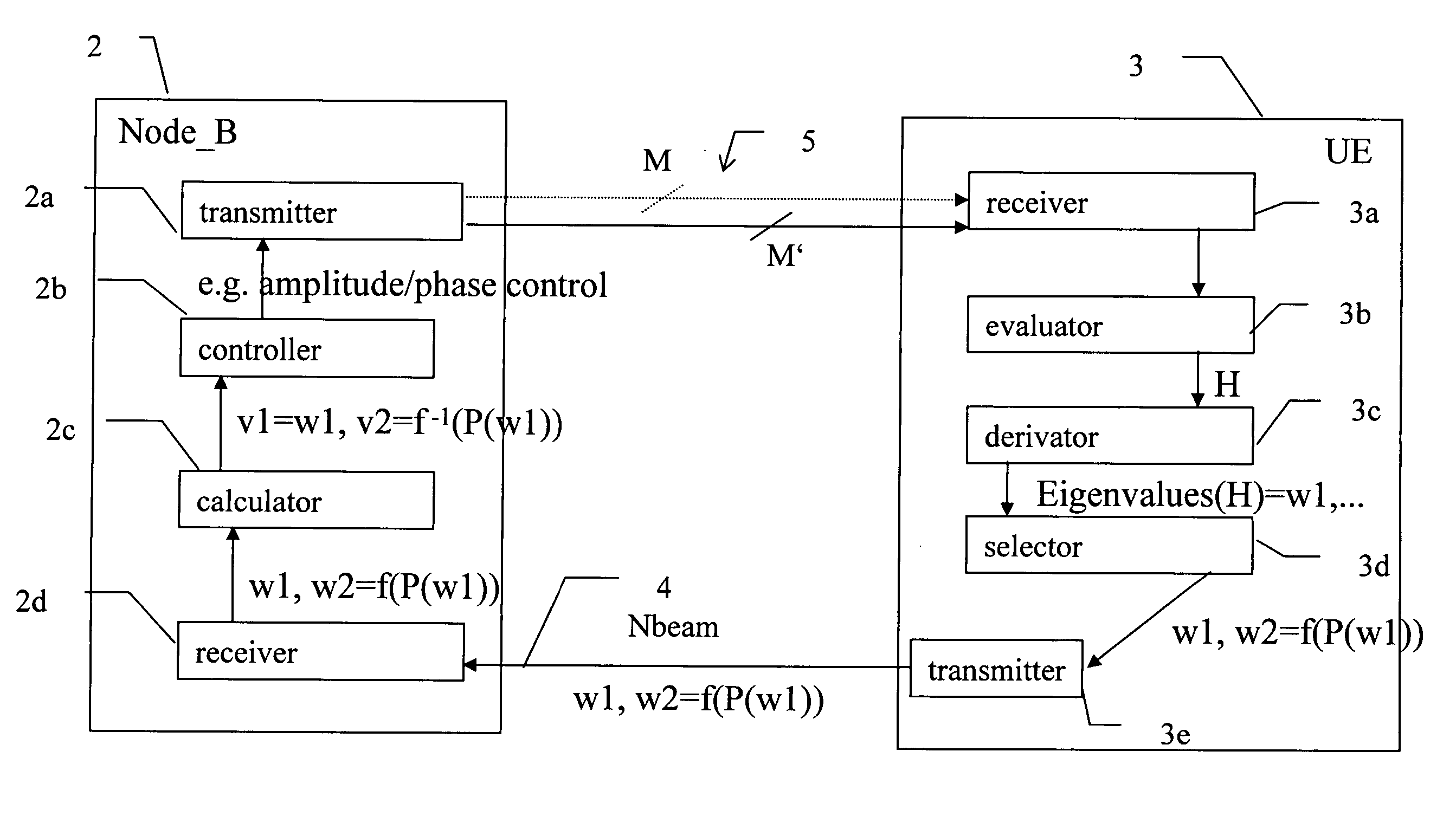
[0128] It is to be noted that—for all embodiments—the signal processings as performed according to the method and described in detail herein are performed by the evaluator 3b, derivator 3c, and selector 3d, respectively (insofar as the UE 3 is concerned) and by the calculator 2c, controller 2b, respectively, as far as the Node_B 2 is concerned. In particular, the implementation of the specific functionality is advantageously effected in hardware as a digital signal processor DSP, or an application specific integrated circuit ASIC, or the like. Such hardware realization is technology independent and can be accomplished using bipolar or MOS, CMOS, BiCMOS technology or others and / or hybrids thereof. In case of a software implementation of the functionalities, this is programming language independe...

Example

[0190] A third specific embodiment will be described in the following. According to the third specific embodiment, the most dominant beam's eigenvector w1 is selected for being fed back to the first transceiver. All coordinates of this vector w1 are transmitted to the Node_B. This provides the advantage that further feedback capacity savings are possible (compared to the first specific embodiment) and that only minimum changes to the feedback path, e.g. in terms of frame structure adopted for signal transmission from the UE to the Node_B are required. In this embodiment, the Node_B has a knowledge of what kind of processing the UE applied. Then, at the Node_B null space projection is applied to the received beamforming information feed back, or the corresponding nullspace basis is calculated Based on received w1, w2 is obtained as in the specific embodiment no. 1, but this information is obtained / calculated but at the Node_B and not transmitted over the feedback path. Thus, at the N...


PUM


Abstract

A closed-loop signalling method controls multiple transmit beams. The method also includes transmitting a plurality of beams from a first transceiver via a plurality of transmission channels to a second transceiver, evaluating, at the second transceiver, characteristics of the plurality of transmitted beams received at the second transceiver. The method also includes deriving, at the second transceiver, beamforming information for being fed back from the second transceiver to the first transceiver based on the evaluated characteristics. The beamforming information is usable for controlling, at the first transceiver, the transmitting of the plurality of beams. The method also includes selecting, at the second transceiver, at least one set of beamforming information for being fed back from the second transceiver via a feedback path to the first transceiver. The method also includes calculating, at the first transceiver, additional beamforming information which was not contained in the feedback path, based on the beamforming information being fed back.

Description

FIELD OF THE INVENTION [0001] The present invention relates to a closed-loop signalling method for controlling multiple transmit beams and correspondingly adapted transceiver devices. BACKGROUND OF THE INVENTION [0002] MIMO (multiple input multiple output) transmission / reception concepts or diversity is used in communication systems such as wireless communication systems in order to enhance communication quality by transmitting information to be transmitted via various (e.g. space and / or time varying) channels. Common to both concepts, MIMO and diversity, is that multiple parallel beams are needed. The expression “beam” as used herein means a spatial transmission channel. [0003] For the sake of keeping the explanations simple, the following description focuses on diversity, while the given explanations are equally applicable to MIMO concepts. [0004] Diversity arrangements can be categorized as open-loop diversity and closed-loop diversity concepts. Also hybrids are possible, which c...

Claims


Application Information

Patent Timeline
IPC IPC(8): H04B1/38
CPCH04B7/0417H04B7/0617H04B7/0634H04B7/0639H04B7/066H04B7/0408H04B7/0695
Inventor HOTTINEN, ARI
Owner NOKIA TECHNOLOGLES OY
Why Eureka
Try Eureka