Apparatus for separating blind source signals having systolic array structure

a technology of blind source signals and arrays, applied in the field of digital signal processing, can solve the problems of large circuit size, long computation time, and many constraints still exist to efficiently transmit or store digital image information, and achieve the effect of low cost and low power consumption

Inactive Publication Date: 2006-05-04
POSTECH ACAD IND FOUND
View PDF4 Cites 9 Cited by
  • Summary
  • Abstract
  • Description
  • Claims
  • Application Information

AI Technical Summary

Benefits of technology

[0018] The present invention provides hardware capable of sepa...

Problems solved by technology

Unfortunately, since a huge amount of data must be processed to handle image signals, many constraints still exist to efficiently transmit or store the digital image information.
In the butterfly structure, since data must be transmitted to an ...

Method used


Image

  • Apparatus for separating blind source signals having systolic array structure
  • Apparatus for separating blind source signals having systolic array structure
  • Apparatus for separating blind source signals having systolic array structure

Examples


Embodiment Construction

[0035] The present invention and operational advantages thereof can be fully understood by referring to the accompanying drawings and explanations thereof.

[0036] Now, exemplary embodiments of the present invention will be described with reference to the accompanying drawings to explain the present invention in detail. In the drawings, the same reference numerals indicate the same elements.

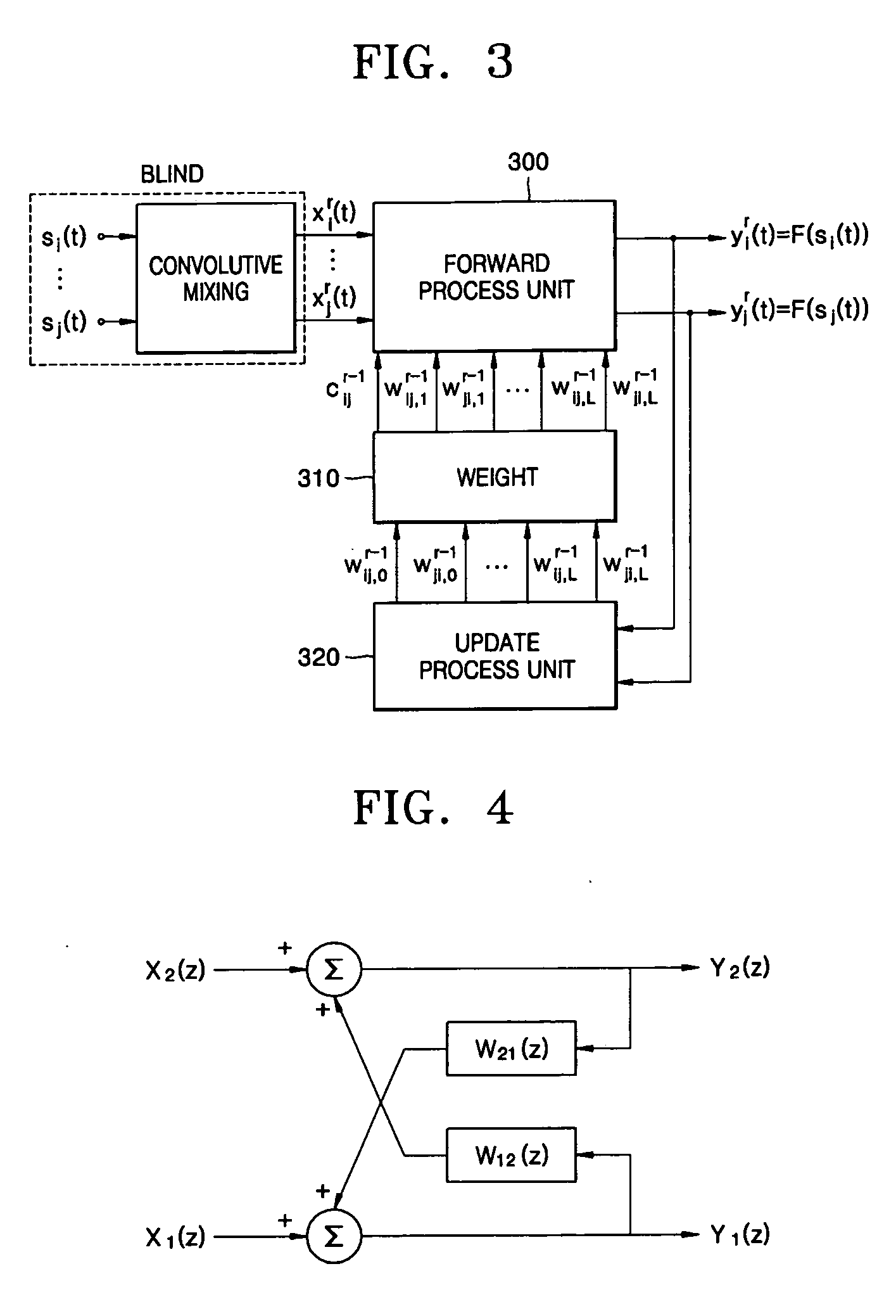
[0037]FIG. 3 is a schematic block diagram conceptually illustrating an apparatus for separating blind source signals according to an embodiment of the present invention, which includes a forward process unit 300, a weight process unit 310, and an update process unit 320.

[0038] Basically, the forward process unit 300 receives n input signal vectors xir(t), . . . , xjr(t) based on Equation 3, which will be described below, and obtains n output signal vectors yir(t), . . . , yjr(t) by multiplying the received input signal vectors xir(t), . . . , xjr(t) by second weight values. The update process un...


PUM


Abstract

Disclosed is a hardware architecture receiving multi-input blind source signals and obtaining multi-output. An apparatus for separating blind source signals includes: a forward process unit receiving a plurality of blind source signal vectors and outputting a plurality of output signal vectors by using a predetermined blind source separation algorithm; an update process unit receiving the plurality of output signal vectors and learning first weighting values used for the predetermined blind source separation algorithm according to a predetermined learning algorithm; and a weight process unit having a matrix operation structure for receiving the first weighting values and converting them into coefficients and second weighting values applicable to the predetermined blind source separation algorithm. The forward process unit includes (L+1) identical processing elements connected in a systolic array structure, where L is the number of sequential delay of blind input signal vectors. The update process unit includes (N2+N)/2×(2L+1) identical updating elements connected in a systolic array structure, where N is the number of the blind input signal vectors. Each cost of the processing elements and the updating elements is initialized by 0 in an initial operation stage.

Description

BACKGROUND OF THE INVENTION [0001] This application claims the priority of Korean Patent Application No. 2004-66168, filed on Aug. 21, 2004, in the Korean Intellectual Property Office, the disclosure of which is incorporated herein in its entirety by reference. [0002] 1. Field of the Invention [0003] The present invention relates to a digital signal processing, and more particularly, to hardware having a systolic array structure for separating multiple input blind source signals. [0004] 2. Description of Related Art [0005] As electronics is advanced, a variety of techniques for processing digital signals in high speed have been developed. At this time, information digitalization is being progressed to meet the future needs for a multimedia era, and, accordingly, information processing technologies have been continuously developed according to corresponding application fields. [0006] The remarkable development in the digital signal processing allows a digital image / video communicatio...

Claims


Application Information

Patent Timeline
IPC IPC(8): G10L15/20
CPCG06K9/624G10L21/028G06V10/7715G06F18/2134G06F17/10
Inventor JEONG, HONGKIM, YONG
Owner POSTECH ACAD IND FOUND
Why Eureka
Try Eureka