Wastewater separator and method of using same

Inactive Publication Date: 2006-05-11
CANPLAS INDS
View PDF30 Cites 4 Cited by
  • Summary
  • Abstract
  • Description
  • Claims
  • Application Information

AI Technical Summary

Benefits of technology

[0008] Therefore, what is desired is a device for effectively separating light waste, such as oil or grease from water. For the purpose of this invention it shall be understood that the term “light waste” shall refer to waste having a specific gravity slightly less than water and which therefore tends to rise when submerged in water. Also the term “heavy waste” shall be used to refer to waste which has a specific gravity which is greater than water, and which therefore tends to sink when placed in water. The desired device according to the present invention should also preferably function so as to prevent solid or heavy waste in the wastewater stream from being trapped in the layer of grease. Finally, the device preferably should not have to be frequently manually emptied of both solid waste and of grease.

Problems solved by technology

Some commercial establishments, such as restaurants, produce a considerable amount of waste or drainage water which often contains high levels of grease or oil.
Such contaminants can adversely affect the sewage treatment plants and can clog up the sewers.
One problem with conventional grease traps is that particles of food are also present in the wastewater stream, such as bits of lettuce, meat and other waste solids.
First, they significantly increase the volume of the waste layer collected.
Second, the bits of solid matter caught in the grease trap tend to decompose, anaerobically, which creates noxious gases, making the job of manually bailing the grease from the grease trap extremely unpleasant.
Thus the prior art devices suffer from being both labour intensive (i.e. they fill quickly and require more frequent cleaning) and extremely unpleasant to maintain.
This is a time-consuming activity, and it must be done fairly frequently to prevent clogging of the inlet pipe.
However, the devices in these patents all suffer from the problem that solid waste is trapped in the trap.

Method used


Image

  • Wastewater separator and method of using same
  • Wastewater separator and method of using same
  • Wastewater separator and method of using same

Examples


Embodiment Construction

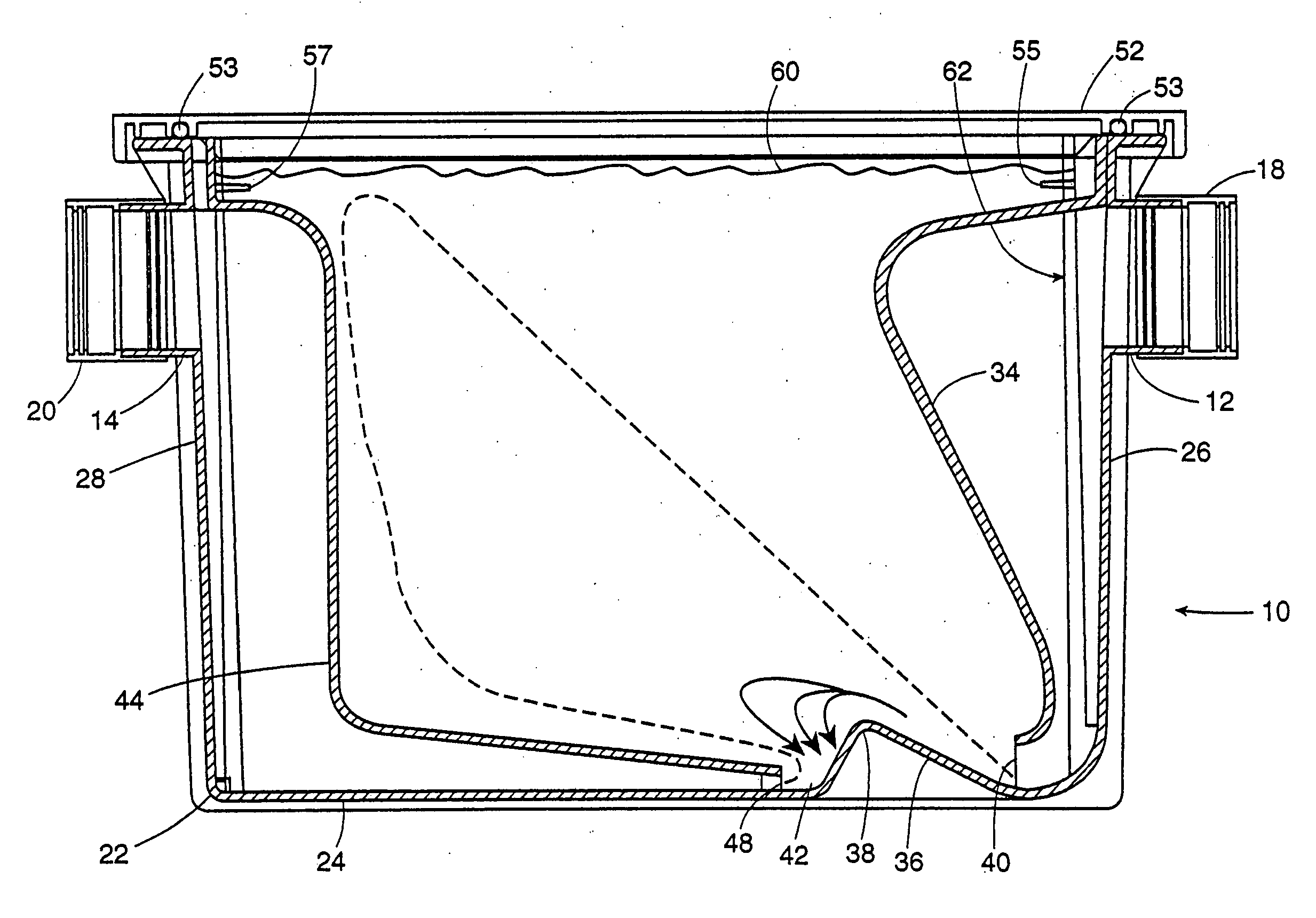
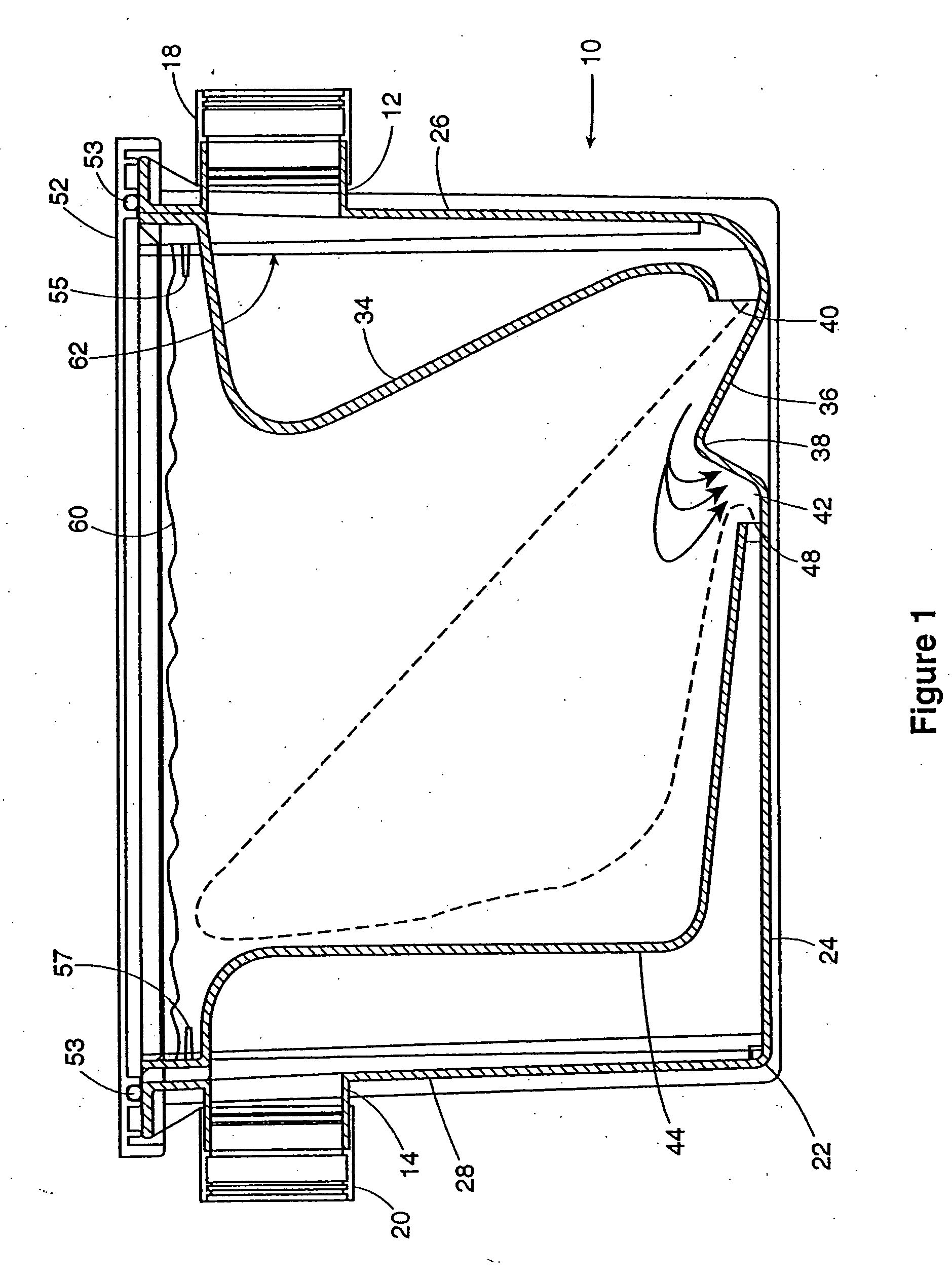
[0036] Referring now to FIG. 1, the wastewater separator is generally designated by reference numeral 10. The wastewater separator 10 is for separating waste from a mixed wastewater stream before the disposal into a sewer system, where the mixed wastewater stream includes heavy waste, light waste and water. “Heavy waste” includes bits of solid food and any other waste with a density greater than that of water. Similarly, “light waste” is any waste in the mixed wastewater stream which has a density less than that of water, such as, for example, grease and oil. It will further be appreciated that the present invention is directed to a self-contained device which is used on an inlet to a sewer system from a commercial or industrial premises involved, typically, in food service preparation.

[0037] The wastewater separator 10 comprises a wastewater inlet 12, a wastewater outlet 14 and a separation container 22. The separation container 22 is filled with water which is the medium typicall...


PUM


Abstract

A method for pretreating a wastewater stream containing grease and food particles before the stream enters a sewer includes the steps of directing said wastewater stream to a separation area; directing said wastewater stream along a preferred flow path within said separation area, said preferred flow path being sized and shaped to permit said grease to rise out of said wastewater stream; trapping said grease which rises out of said wastewater stream; extending a wastewater outlet substantially across said separation area; accelerating said remaining wastewater, carrying said food particles, through said outlet from said separation area, thereby sucking said food particles away from said separation area; and directing said wastewater and said food particles toward said sewer system.

Description

CROSS-REFERENCE TO RELATED APPLICATIONS [0001] This application is a divisional of application Ser. No. 09 / 732,299, filed Dec. 8, 2000, which claims the benefit of Canadian Application No. CA 2,299,134, filed Feb. 23, 2000, the contents of all of which are incorporated herein by reference.FIELD OF THE INVENTION [0002] This invention relates to the field of wastewater management, and, in particular, to devices known as grease traps, which are used for separating grease and oil from wastewater before permitting the wastewater to enter into a sanitary or storm sewer systems. BACKGROUND OF THE INVENTION [0003] Some commercial establishments, such as restaurants, produce a considerable amount of waste or drainage water which often contains high levels of grease or oil. Such contaminants can adversely affect the sewage treatment plants and can clog up the sewers. Therefore, most jurisdictions require that such grease and oil be removed from the wastewater at the commercial establishment b...

Claims


Application Information

Patent Timeline
IPC IPC(8): C02F1/24B01D17/02B01D21/24E03F5/16
CPCB01D17/0205B01D21/0042B01D21/2405B01D21/2444B01D2221/02B01D2221/06E03F5/16B01D17/0208B01D17/0211B01D17/0214
Inventor BROEDERS, NICHOLASMANTYLA, JAMESBALDWIN, SCOTTMERRINGTON, DAN
Owner CANPLAS INDS
Why Eureka
Try Eureka