Twist waveguide and radio device

Inactive Publication Date: 2006-05-11
MURATA MFG CO LTD
View PDF3 Cites 14 Cited by
  • Summary
  • Abstract
  • Description
  • Claims
  • Application Information

AI Technical Summary

Benefits of technology

[0011] According to the present invention, a connection element disposed between first and second rectangular propagation path elements is provided with projections projected inward so as to face each other. Thus, an electric field of an electromagnetic wave entering from the first or second rectangular propagation path element is concentrated in the projections, and a plane of polarization of the electromagnetic wave propagating through the connection element is rotated. Consequently, the plane of polarization is rotated in the connection element from the first rectangular propagation path element towards the second rectangular propagation path element or from the second rectangular propagation path element towards the first rectangular propagation path element. Since such a structure does not require a resonant window or a filter window shown in FIG. 15, a wide frequency range characteristic can be achieved. Furthermore, according to this structure, since the plane of polarization is not rotated by a rectangular waveguide whose overall structure is twisted, the plane of polarization of an electromagnetic wave can be rotated within a narrow space.
[0012] Furthermore, according to the present invention, an inner periphery of the connection element may be provided with surfaces substantially parallel to H plane and E plane of the first rectangular propagation path element. Specifically, the surfaces form a staircase such that abutting sections between the surfaces parallel to H plane and the surfaces parallel to E plane constitute the projections. Moreover, the staircase may be inclined in a direction corresponding to a direction in which H plane of the second rectangular propagation path element is inclined. Accordingly, each of the elements can be formed only of flat surfaces and parallel surfaces, whereby the manufacturing process for the first and second rectangular propagation path elements and the connection element is simplified. This reduces the manufacturing cost, and therefore, contributes to the reduction of the overall cost.
[0013] Furthermore, according to the present invention, the projections may include two projections such that a plane extending between the two projections may be inclined towards E plane of the second rectangular propagation path element with respect to E plane of

Problems solved by technology

Since a rapid twisting of a twisted waveguide having such a structure is not allowed during its manufacturing process, the waveguide requires a pre

Method used


Image

  • Twist waveguide and radio device
  • Twist waveguide and radio device
  • Twist waveguide and radio device

Examples


Example

[0043] A twisted waveguide according to a first embodiment will now be described with reference to FIGS. 1 to 3.

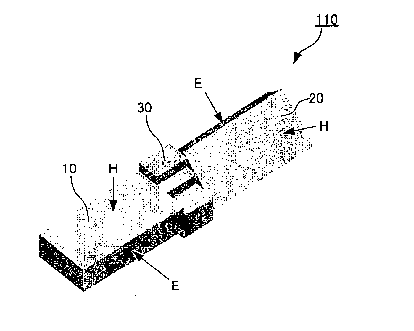
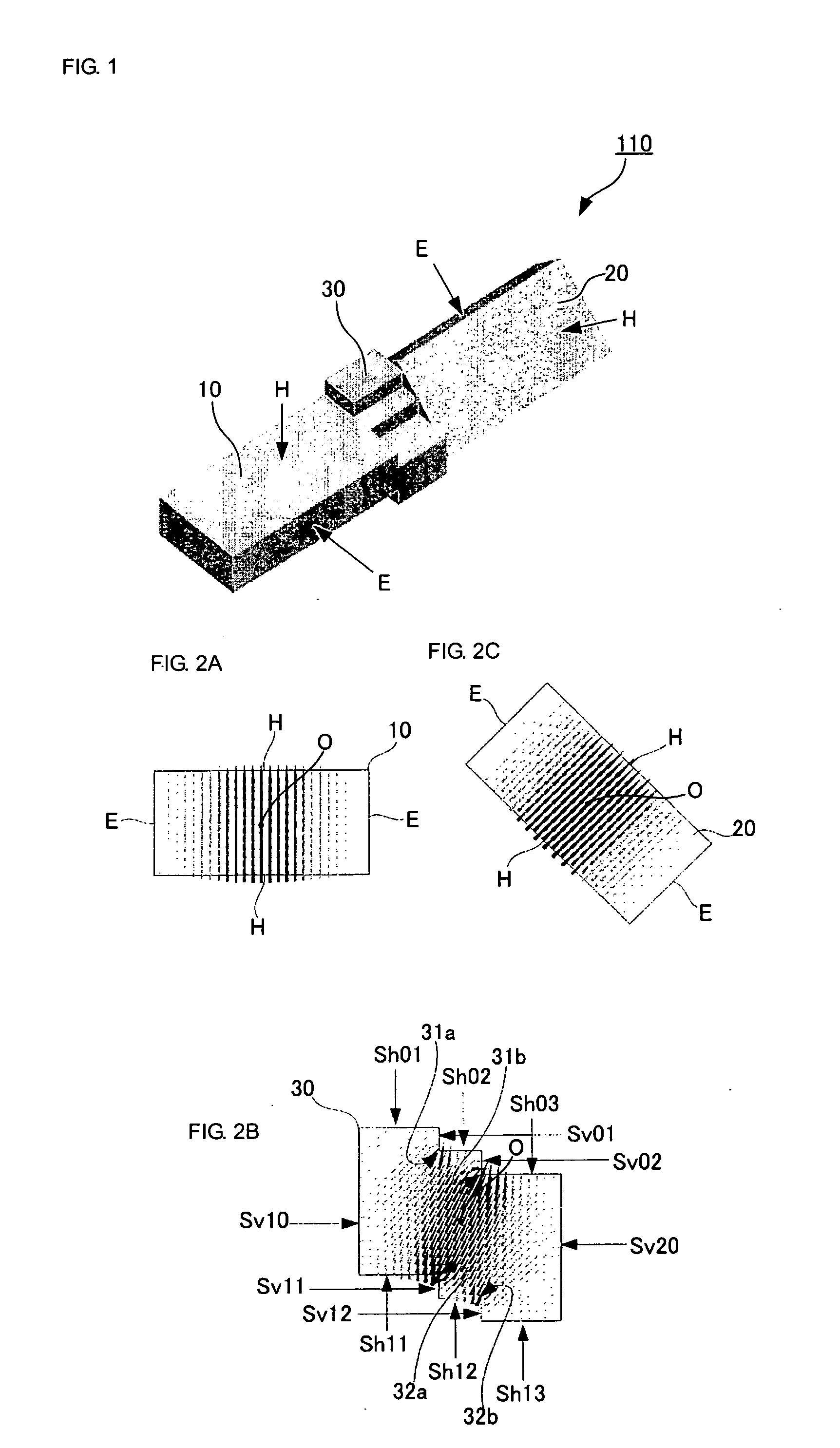
[0044]FIG. 1 is a perspective view illustrating a three-dimensional configuration of an inside (electromagnetic-wave propagation path) of a twisted waveguide. A twisted waveguide 110 includes a first rectangular waveguide element 10 corresponding to a first rectangular propagation path element according to the present invention; a second rectangular waveguide element 20 corresponding to a second rectangular propagation path element according to the present invention; and a connection element 30. The first rectangular waveguide element 10 and the second rectangular waveguide element 20 propagate an electromagnetic wave of TE10 mode and each have an H plane extending longitudinally and an E plane extending laterally when viewed in cross section taken along a plane perpendicular to a direction of electromagnetic-wave propagation. The reference characters H in FIG. 1 each ind...

Example

[0053]FIG. 4 includes diagrams illustrating a twisted waveguide according to a second embodiment. Diagrams (A) and (B) are cross-sectional views of connection elements having different structures taken along a plane perpendicular to the direction of electromagnetic-wave propagation, one of the connection elements being included in the twisted waveguide. In contrast to the first embodiment shown in FIGS. 1 and 2 provided with two pairs of projections (a total of four projections) projected inward to face each other, the example shown in diagram (A) is provided with three pairs of projections (a total of six projections). Furthermore, the example shown in diagram (B) is provided with five pairs of projections (a total of 10 projections). Accordingly, the connection element 30 may be provided with a desired number of projections.

Example

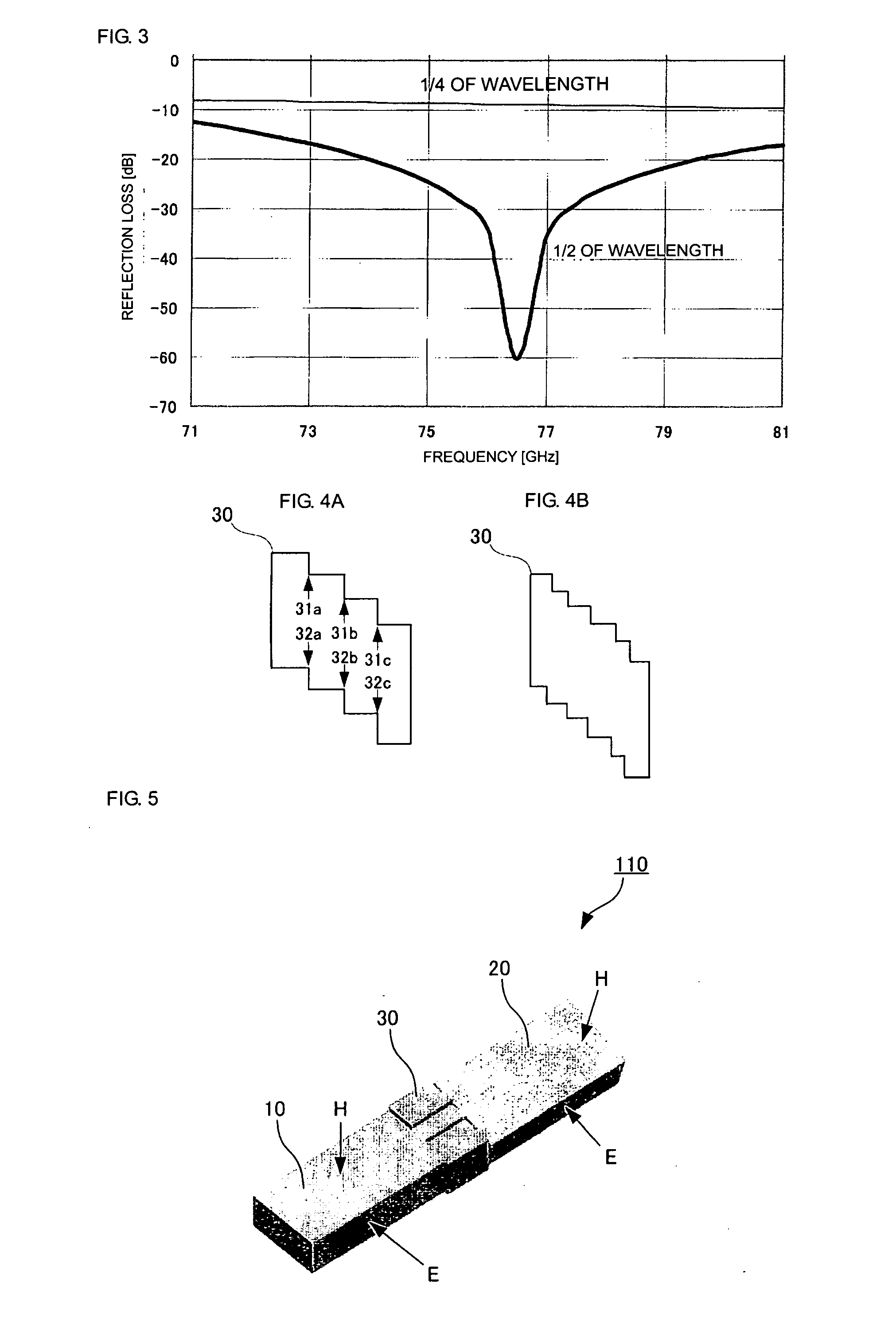
[0054]FIG. 5 illustrates a twisted waveguide according to a third embodiment. In this embodiment, H plane of the second rectangular waveguide element 20 is inclined at an angle of 15° with respect to H plane of the first rectangular waveguide element 10. This means that the connection element 30 rotates the plane of polarization of an electromagnetic wave propagating through the connection element 30 by an angle of 15°. Consequently, when the rotation angle is to be reduced, the angle of inclination of the staircase portion of the connection element 30 is made smaller, whereby the height of each step of the staircase is reduced. In contrast, if the rotation angle is to be increased, the angle of inclination of the staircase portion of the connection element 30 is made larger, whereby the height of each step of the staircase is increased.


PUM


Abstract

H plane and E plane of a second rectangular waveguide element are inclined at an angle of 45° with respect to H plane and E plane of a first rectangular waveguide element. A connection element disposed between the first and second rectangular waveguide elements has an inner periphery that surrounds a central axis extending in a direction of electromagnetic-wave propagation. The inner periphery includes surfaces parallel to H plane and E plane of the first rectangular propagation path element, and these surfaces form a staircase such that abutting sections between the surfaces parallel to H plane and the surfaces parallel to E plane constitute projections. The staircase is inclined in a direction corresponding to a direction in which H plane of the second rectangular propagation path element is inclined. Accordingly, an electric field is concentrated in the projections of the connection element (30), and a plane of polarization of an electromagnetic wave propagating through the connection element is rotated from a plane of polarization in the first rectangular waveguide element towards a plane of polarization in the second rectangular waveguide element.

Description

TECHNICAL FIELD [0001] The present invention relates to a twisted waveguide that is capable of rotating a plane of polarization of an electromagnetic wave propagating through two rectangular propagation path elements. BACKGROUND ART [0002]FIG. 14 illustrates a most-commonly-used conventional twisted waveguide, which is a rectangular waveguide having a twisted structure. Since a rapid twisting of a twisted waveguide having such a structure is not allowed during its manufacturing process, the waveguide requires a predetermined length in the propagation direction of an electromagnetic wave. Moreover, the waveguide also requires a large space in the joint portions. Patent Document 1 discloses a structure for solving these problems. Specifically, FIG. 15 illustrates the structure of a twisted waveguide according to Patent Document 1. In this twisted waveguide, a second rectangular waveguide element 2 is attached in a manner such that the second rectangular waveguide element 2 is inclined...

Claims


Application Information

Patent Timeline
IPC IPC(8): H01P1/165H01P1/02
CPCH01P1/022
Inventor NAGAI, TOMOHIRO
Owner MURATA MFG CO LTD
Why Eureka
Try Eureka