Traffic control method for network equipment

a traffic control and network equipment technology, applied in data switching networks, memory adressing/allocation/relocation, digital transmission, etc., can solve the problems of increased power consumption, excessive network processor size, and drop in so as to reduce power consumption and avoid the effect of dropping throughput in network equipmen

Inactive Publication Date: 2006-05-11
HITACHI LTD
View PDF10 Cites 57 Cited by
  • Summary
  • Abstract
  • Description
  • Claims
  • Application Information

AI Technical Summary

Benefits of technology

[0026] Utilizing the traffic manager of this invention in network equipment possessing a packet processor utilizing a cache, such as a cache-based network processor, produces the effect that a drop in the cache-hit rate dependent on the process-cache packet arrival sequence can be prevented, and, consequently, a drop

Problems solved by technology

However, raising the network processor throughput and utilizing even faster high-speed network interfaces requires techniques to increase the number of packet processing engines inside the network processor.
Using more packet processing engines makes the network processor size excessive and causes an increased power consumption.
When configuring network equipment from cache-based network processors, the cache-hit rate drops accor

Method used


Image

  • Traffic control method for network equipment
  • Traffic control method for network equipment
  • Traffic control method for network equipment

Examples


first embodiment

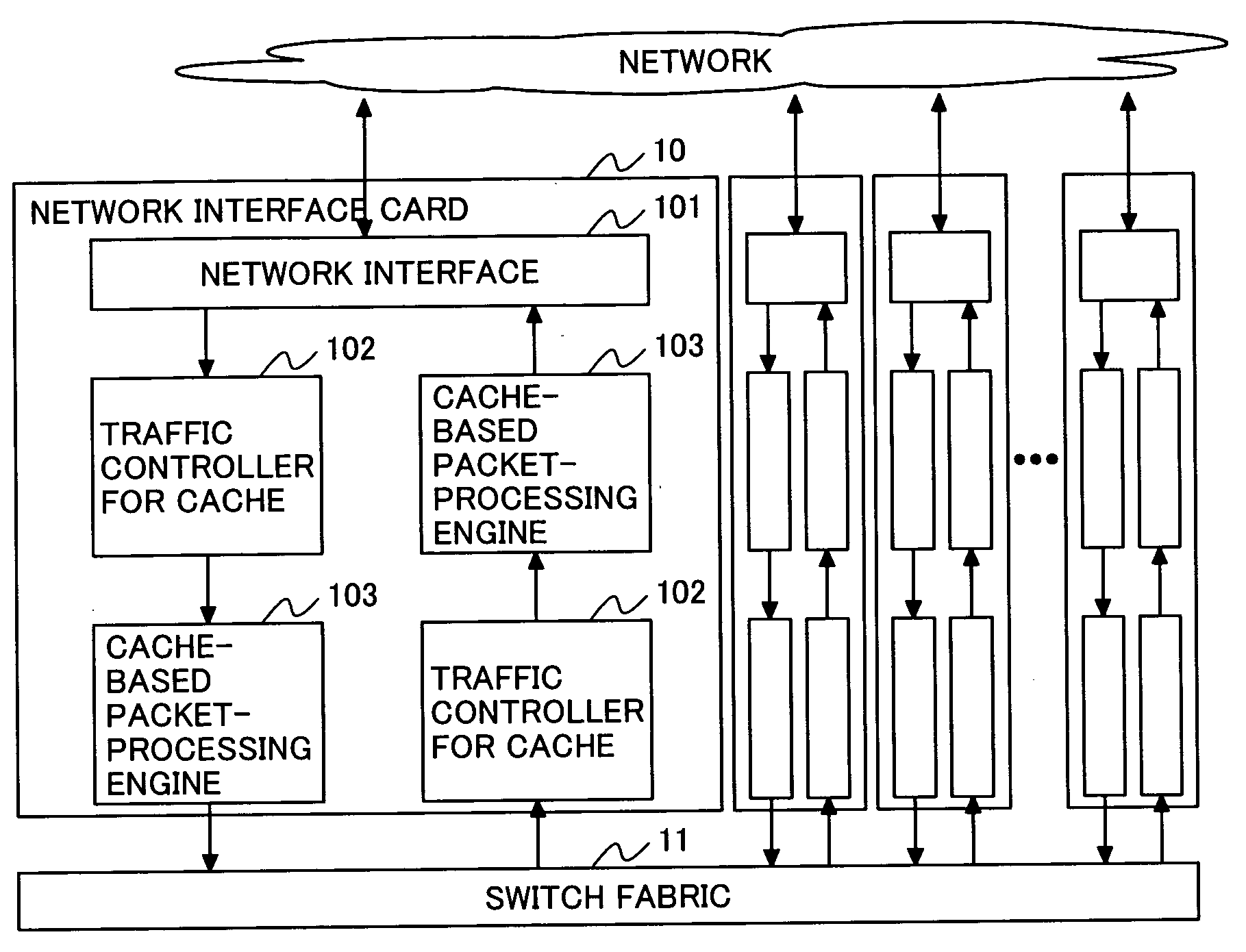
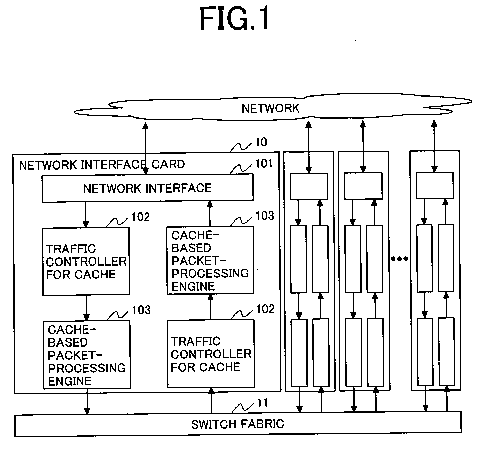
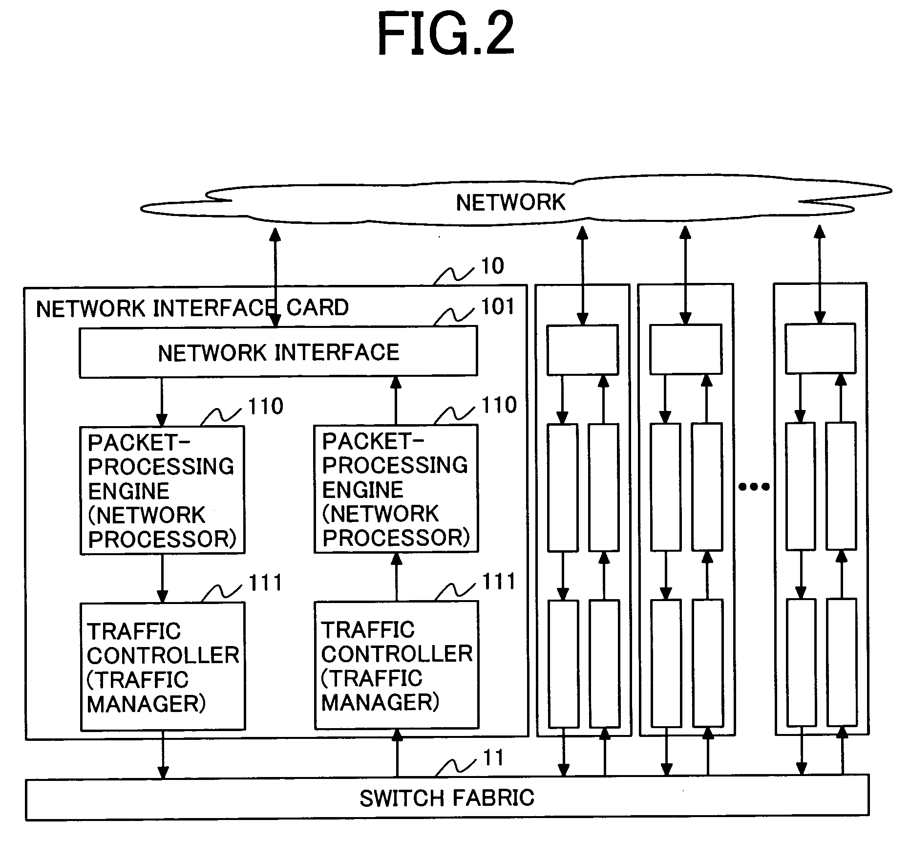
[0045]FIG. 1 is a block diagram of network equipment in accordance with the present embodiment.

[0046] In this embodiment, the network equipment is comprised of a network interface 101 for sending and receiving packets from the network, a traffic controller 102 for the cache for controlling the network traffic, a cache-based packet processor 103, a network interface card 10 containing the elements 101, 102, 103, and a switch fabric 11 for coupling multiple network interface cards 10 and for exchanging packets. Also included are interfaces between host processors and host processors for centralized control of path information between the multiple network interface cards 10.

[0047] An overall description of the packet processing operation and its effect in this embodiment will be described next. The packet processor (or packet processing engine) receives the packets from the network interface 101, and the cache traffic controller 102 separates the packets into groups called flows, and...

second embodiment

[0101] When utilizing the cache, multiple data of different types tends to concentrate at the same entries to the cache memory, and this causes a state called thrashing to occur where data will mutually overwrite each other, thereby destroying the cache entries. Consequently, frequently interchanging the cache entries will cause a drop in cache utilization efficiency. The (N-way) Set Associative method process cache and its FIFO queues for the traffic manager, as described in conjunction with the first embodiment, are contrived to reduce thrashing, but they might be inadequate to inhibit thrashing in small N values that are mountable in designated entries.

[0102] Therefore, in order to prevent a drop in performance due to thrashing, the cache traffic controller of the second embodiment of this invention contains a small volume fully associative process cache and FIFO queues and tags for the small volume fully associative process cache.

[0103] The fully associative process cache is a...

third embodiment

[0110] The first embodiment and the second embodiment implement the mounting efficiency and are based on examples in which the process-cache memory tag is separate from the cache-based packet processor, and it is installed in the traffic controller for cache. The cache-based packet processor 103 may be a type that completely contains both the tags and the data section of the process-cache memory. As seen in FIG. 13, the third embodiment is a structure where the process-cache memory of the cache-based packet processor 103 possesses a tag (section) as well as a data section. The cache traffic controller 102 in the third embodiment possesses a structure identical to that of the first embodiment or second embodiment; however, when the output data generator 204 conveys information to the cache-based packet processor 103, the unique information 401, the analyzed information 402 and the extracted information 403 are removed from the format 450 of FIG. 4.

[0111] The cache-based packet proce...


PUM


Abstract

A function block containing a process-cache tag for storing process-cache tags in the pre-stage of a process cache and an FIFO queue for each tag entry are installed as a traffic controller. The traffic controller stacks packet groups, identified as being from the same flow, in the same FIFO queue. Each FIFO queue records the logged state of the corresponding process queues, and when a packet arrives at an FIFO queue entry in a non-registered state, only its first packet is conveyed to a function block for processing the process-cache misses, and then it awaits registration in a process cache. Access to the process cache from the FIFO queue is implemented at the time that registration of the second and subsequent packets in the process cache are completed. This allows packets other than the first packet in the flow to always access the process cache for a cache hit.

Description

CLAIM OF PRIORITY [0001] The present application claims priority from Japanese application JP 2004-321458, filed on Nov. 5, 2004, the content of which is hereby incorporated by reference into this application. FIELD OF THE INVENTION [0002] The present invention relates to in general a method to be used for configuring network equipment, such as routers and switches, for low-delay switching systems for large volume packets. The present invention relates, in particular, to a technology for providing basic components of network equipment that is effective for regulating traffic for an ASIC (Application Specific Integrated Circuit) and network processors for processing of MAC frame (Media Access Control) and IP (Internet Protocol) packets utilizing caches. BACKGROUND OF THE INVENTION [0003] In the communications field, network equipment, such as routers and switches, are utilized for establishing a connection between multiple networks. The network equipment carries out communications by...

Claims


Application Information

Patent Timeline
IPC IPC(8): H04L12/28G06F12/08H04L12/931
CPCH04L49/90H04L49/9036H04L49/9094
Inventor OKUNO, MICHITAKA
Owner HITACHI LTD
Why Eureka
Try Eureka