
Implantable stent with modified ends

a technology of endolumenal stents and implants, which is applied in the field of implantable endolumenal stents, can solve the problems of significant burden, proximal end trauma, and balloon end trauma to localized vessel wall trauma, so as to enhance long-term patency, improve tissue-device interactions, and improve long-term patency

Inactive Publication Date: 2006-05-11
MEDLOGICS DEVICE CORP
View PDF57 Cites 88 Cited by
  • Summary
  • Abstract
  • Description
  • Claims
  • Application Information

AI Technical Summary

Benefits of technology

[0033] One aspect of the invention is an implantable endolumenal stent assembly that is adapted to provide improved long-term patency specifically along or adjacent to the proximal upstream end of the stent.
[0038] Another aspect of the invention is an implantable stent with a unique local structure at the ends of the stent that is adapted to improve the tissue-device interactions at the stent ends.
[0039] Another aspect of the invention is an implantable stent with at least one unique local structure specifically at the proximal crowns at the proximal end of the stent that is adapted to improve long-term patency along proximal vessel wall segment associated with the stented lesion.
[0040] Another aspect of the invention is an implantable stent with a unique local structure along the proximal end of the stent versus the distal end of the stent, which unique local structure at the proximal end is adapted to enhance long term patency at the proximal stent end at least in part at the expense of increased profile versus the distal end of the stent.

Problems solved by technology

Else, a stent that substantially shortens during balloon expansion exposes the balloon ends to localized vessel wall trauma at those ends without the benefit of the stent scaffolding to hold those regions open long-term after the intervention is completed.
However, these efforts carry significant burden peri-operatively in handling and disposing of the materials, and results have yet been considered compelling among the healthcare community.
However, the proximal end has not been in particular addressed as a location with unique requirements, nor have unique structures been incorporated locally only at the proximal end.
Notwithstanding these substantial improvements that appear to be anticipated in view of the recent sirolimus and paclitaxel DES clinical experiences, however, various needs still remain and are believed to be unmet by these and other previously disclosed DES efforts.
Therefore, these mechanical structures, typically constructed of stainless steel, cobalt-chromium, or other strong metals, result in abrupt transitions with adjacent, unstented vessel wall.
To the extent that injury is done adjacent to but beyond the ends of stents, such injury is not receiving the benefit of drug delivery from the struts as is experienced within the longitudinal confines of the implant.
However, previously disclosed DES efforts provide a constant dose along the stent, and harm may result from overdosing the subject drugs, many of which are toxic at certain levels.
To provide the dose necessary to “reach” the upstream tissue via diffusion would potentially provide too much drug along the stent, with possible harm including tissue necrosis and possibly aneurysms resulting from negative remodeling around the “high dose” stent.
However, these disclosures have yet to address the unique biomechanical requirements located at the proximal, upstream end of the stent.
Few practitioners specifically attempt to avoid such stent overlap, however, based upon the belief that such overlap causes more harm than benefit.
More specifically, the combination, overlapping lattice structure that results from overlapping two opposing stents is in particular undesirable within a blood pool, such as in an artery, where poor fluid dynamics along the stented wall are compounded by the overlapped region, possibly resulting in an increased risk of thrombogenesis in that area.

Method used


Image

  • Implantable stent with modified ends
  • Implantable stent with modified ends
  • Implantable stent with modified ends

Examples


Embodiment Construction

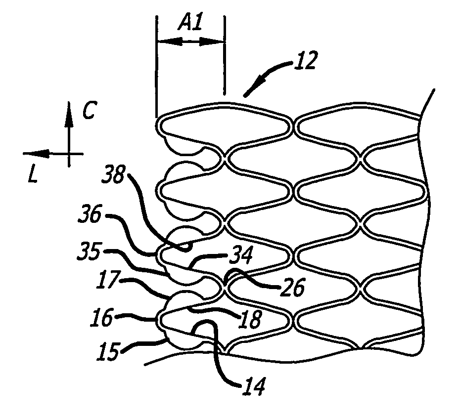
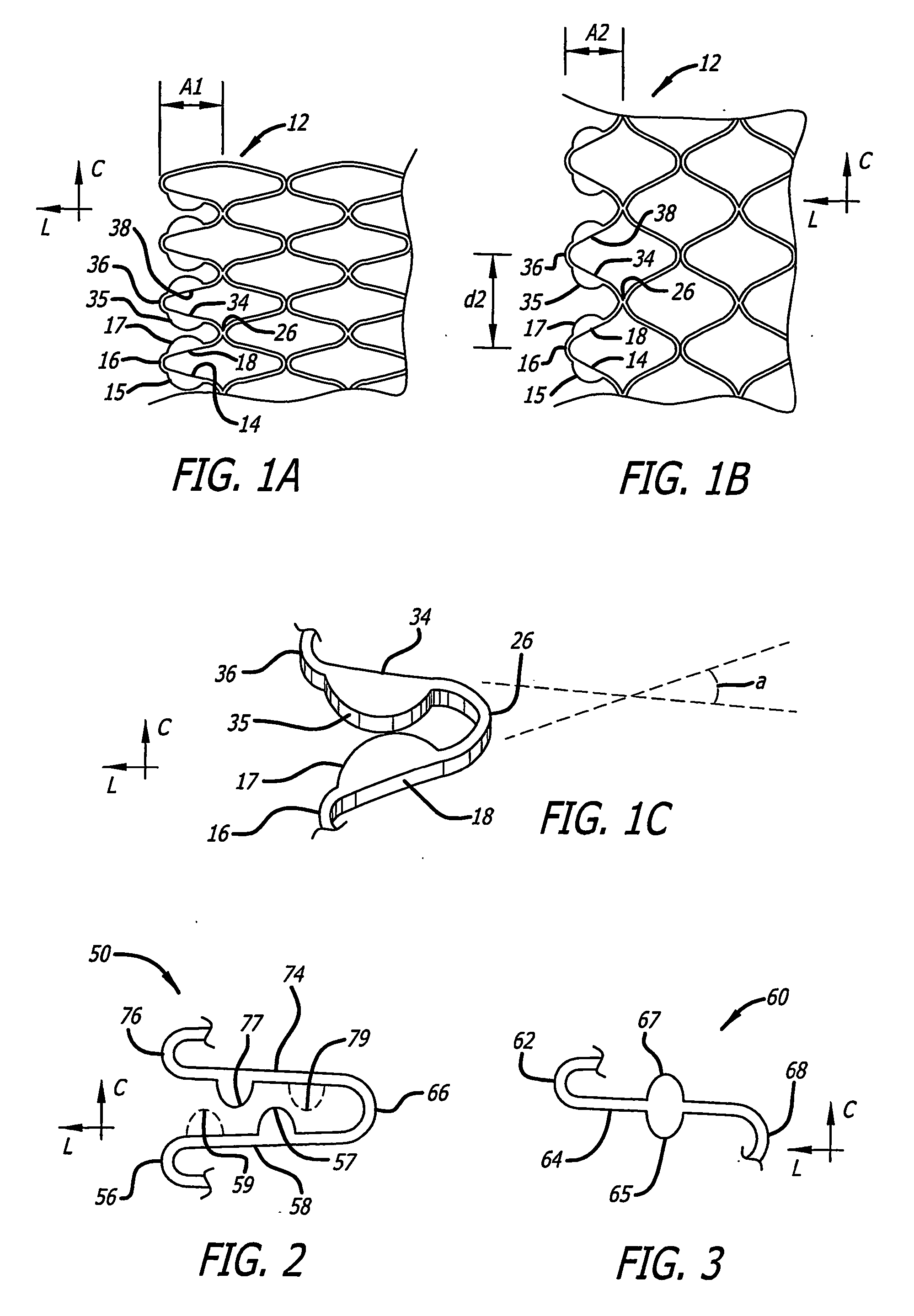
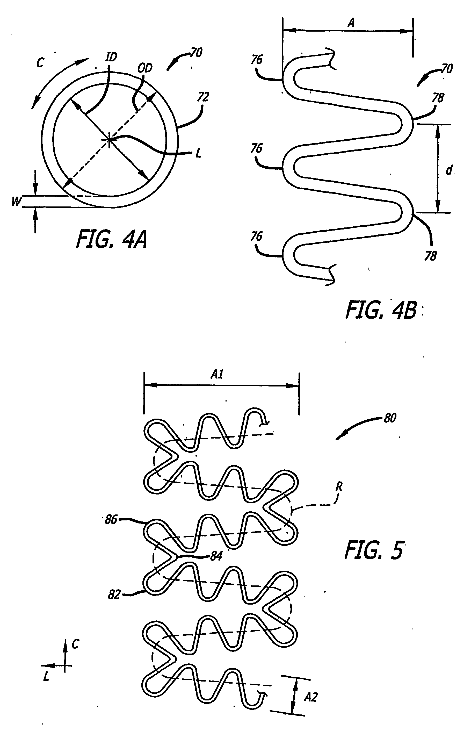
[0121] Referring more specifically to the drawings, for illustrative purposes the present invention is embodied in the apparatus generally shown in FIG. 1A through FIG. 38. In general, it is to be appreciated that the various embodiments provide enhancements for improved outcomes for drug eluting stents, wherein a stent scaffolding is adapted to carry and elute bioactive agents. Such may be provided for example in or as a coating along surfaces of the stent scaffolding, or in wells or cavities formed along the stent scaffolding, that hold and elute the drugs. These various enhancements are not intended to be limited to a particular modality of such drug carrying mode, and other modes than those specifically described are contemplated as would be apparent to one of ordinary skill based upon review of this disclosure in view of other available information related to drug eluting stents. It is further appreciated that, despite the various benefits afforded by the present enhancements t...


PUM


Abstract

A stent is provided with modified ends (782, 786) and enhanced drug delivery. The stent assembly also provides for enhanced overlapping between adjacent stents.

Description

BACKGROUND OF THE INVENTION [0001] 1. Field of the Invention [0002] This invention is an implantable medical device and related methods of manufacture and use. More specifically, it is an implantable endolumenal stent. [0003] 2. Description of the Background Art [0004] Implantable stents have been under significant development for more than a decade, and many different designs have been investigated and made commercially available for use in providing mechanical scaffolding to hold body lumens open or “patent.” Stents are generally used in many different body lumens, including in particular blood vessels, and more specifically coronary and peripheral arteries. Other body lumens where stents have been disclosed for use include pulmonary veins, gastrointestinal tract, biliary duct, fallopian tubes, and vas deferens. Still further, artificial lumens have been created in the body in a man-made effort to provide artificial communication or transport within the body, such as for example s...

Claims


Application Information

Patent Timeline
Patent Type & Authority Applications(United States)
IPC IPC(8): A61F2/06A61F2/00A61F2/82
CPCA61F2/91A61F2/915A61F2002/826A61F2002/91508A61F2002/91516A61F2230/0013A61F2002/91533A61F2002/91558A61F2250/0035A61F2250/0067A61F2002/91525
Inventor PEACOCK, JAMES C. IIIMAIER, NATHAN C.
Owner MEDLOGICS DEVICE CORP
Learn More