Torque controller for internal combustion engine

a technology of torque controller and internal combustion engine, which is applied in the direction of electric control, ignition automatic control, machines/engines, etc., can solve the problems of deteriorating fuel economy, too large amount of ignition retard, and inability to control the ignition timing, so as to achieve the effect of restricting the increment of exhaust gas temperatur

Inactive Publication Date: 2006-05-18
DENSO CORP
View PDF5 Cites 37 Cited by
  • Summary
  • Abstract
  • Description
  • Claims
  • Application Information

AI Technical Summary

Benefits of technology

[0011] Because the offset amount of the ignition timing in the retard direction can be computed without the estimated torque which is determined based on the intake air flow rate including the leak air, it is restricted that the ignition retard amount becomes too

Problems solved by technology

Because the offset amount of the ignition timing in the retard direction can be computed without the estimated torque which is determined based on the intake air flow rate including the leak air, it is restricted that the ignition retard amount becomes too lar

Method used


Image

  • Torque controller for internal combustion engine
  • Torque controller for internal combustion engine
  • Torque controller for internal combustion engine

Examples


first embodiment

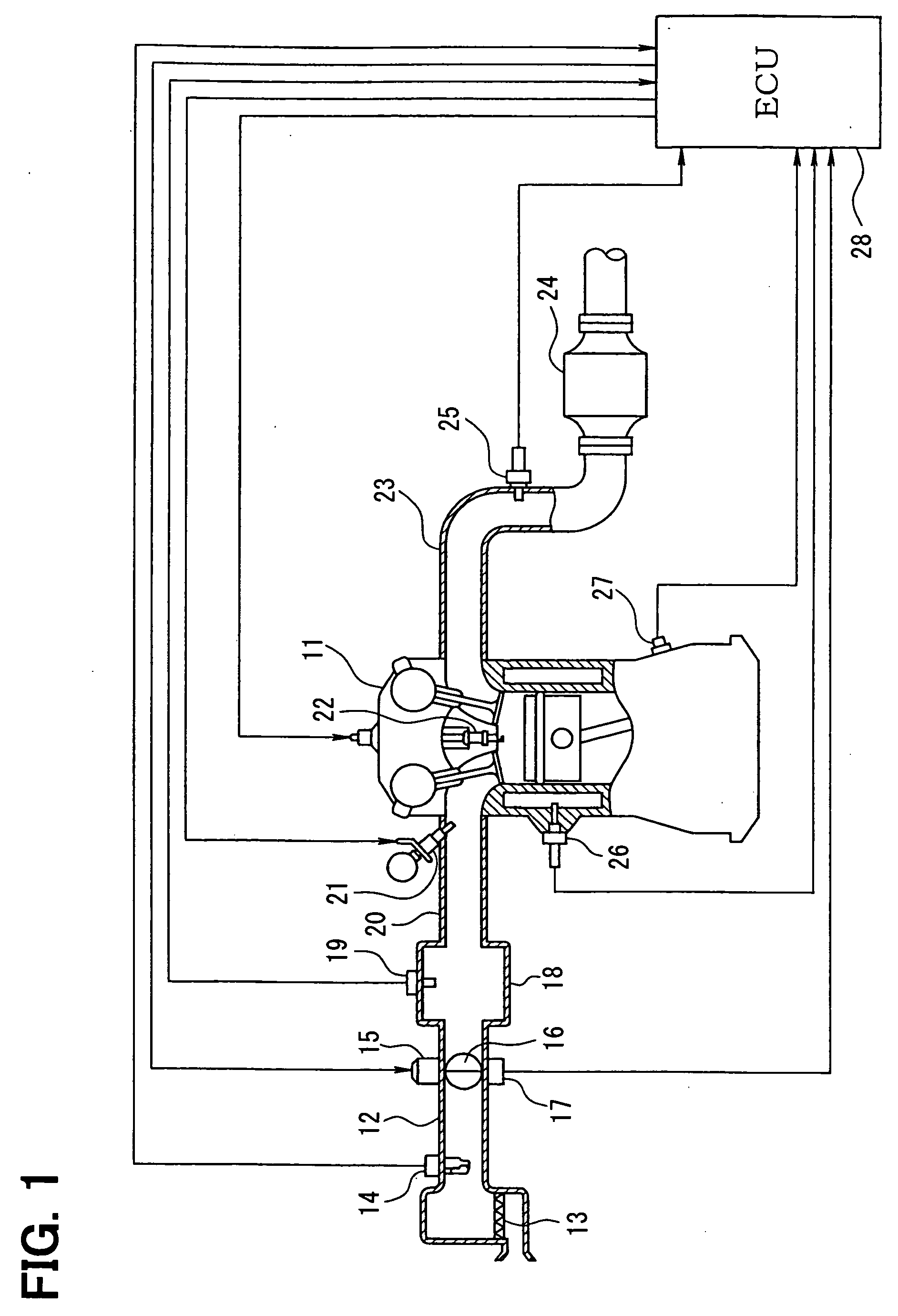
[0021] Referring to FIGS. 1 to 3, a structure of an engine control system is described hereinafter. An air cleaner 13 is arranged upstream of an intake pipe 12 of an internal combustion engine 11. An airflow meter 14 detecting an intake air flow rate is provided downstream of the air cleaner 13. A throttle valve 16 driven by a DC-motor 15 and a throttle position sensor 17 detecting a throttle position are provided downstream of the air flow meter 14.

[0022] A surge tank 18 including an intake air pressure sensor 19 is provided down steam of the throttle valve 16. The intake air pressure sensor 19 detects intake air pressure. An intake manifold 20 is connected to the surge tank 18. A fuel injector 21 is mounted on the intake manifold 20 at a vicinity of an intake air port. A spark plug 22 is mounted on a cylinder head of the engine 11 corresponding to each cylinder to ignite air-fuel mixture in each cylinder.

[0023] An exhaust pipe 23 of the engine 11 is provided with a three-way cat...

second embodiment

[0039] Referring to FIGS. 6 and 7, a second embodiment is described hereinafter.

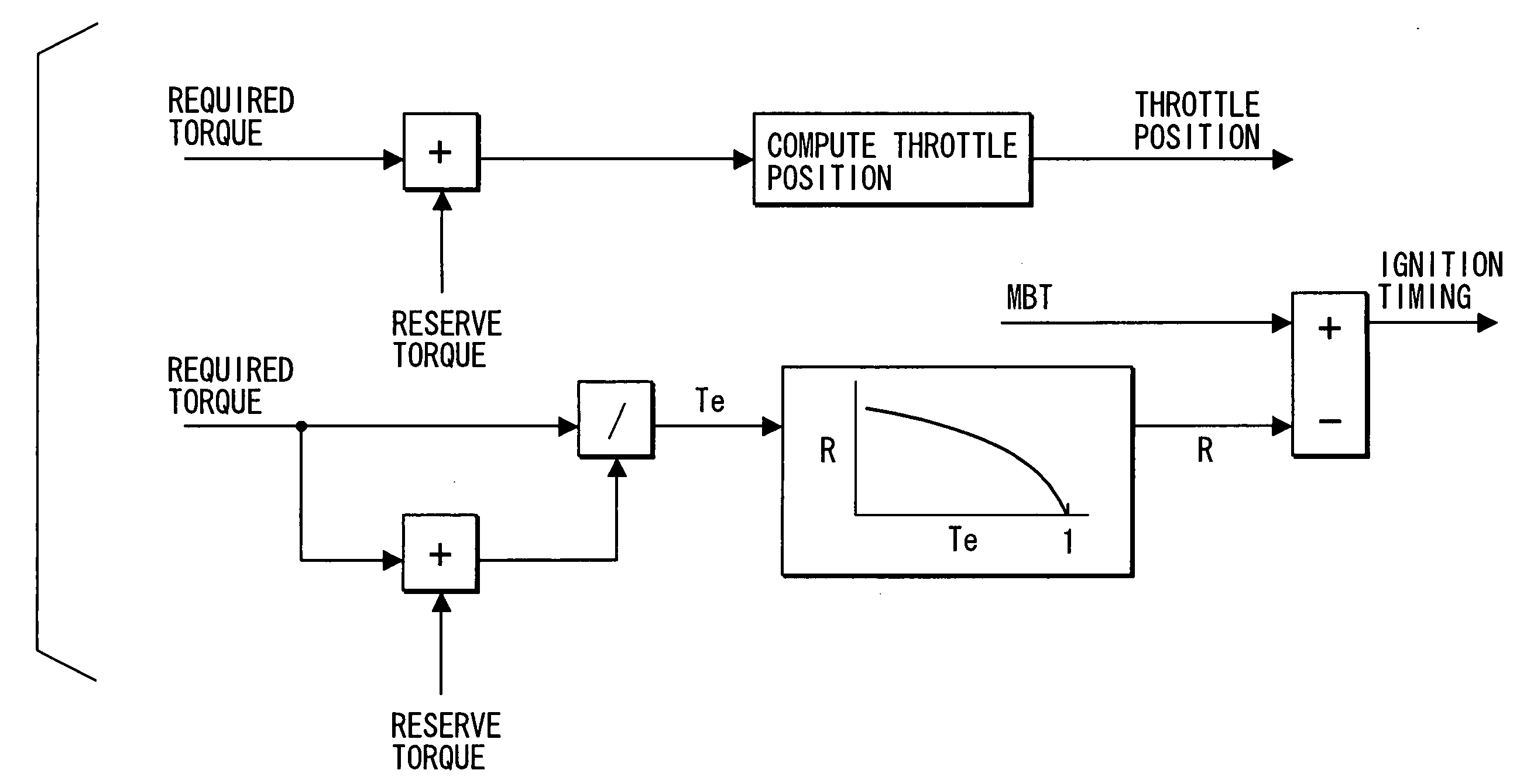
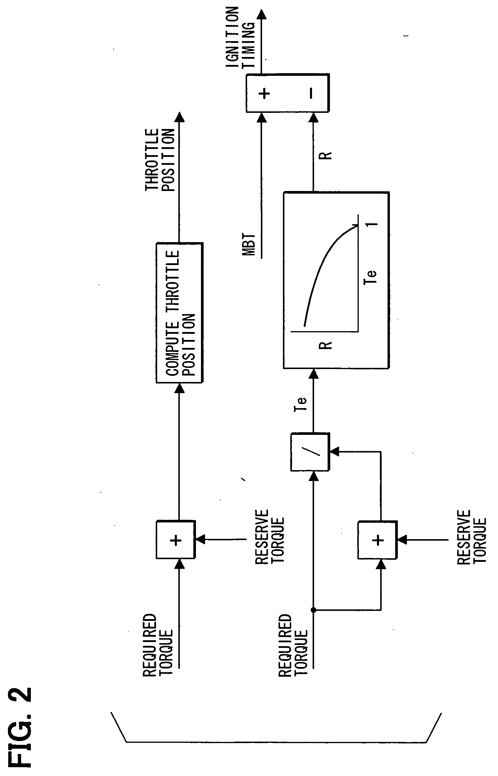
[0040] In a torque reserve control according to the second embodiment, when the ignition retard amount R is computed based on the ratio (torque efficiency Te) between the required torque and the R-R torque, a responsiveness of the R-R torque relative to the required torque is reduced, and effects of an integration term of the feedback correction amount by the ISC, which is referred to as ISC integration term hereinafter, and a learning value of the feedback correction amount by the ISC, which is referred to as ISC learning value hereinafter, are eliminated from the required torque and the R-R torque.

[0041] Specifically, when the ignition timing is computed, the effects of the ISC integration term and the ISC learning value are eliminated from the required torque which is computed based on the increment / decrement in torque by the ISC.

[0042] Besides, the responsiveness of the R-R torque relative to the ...

third embodiment

[0050] Generally, in a catalyst quick warm-up control, the ignition timing is retarded in order to increase the exhaust gas temperature. In the situation that the normal torque reserve control is performed during the catalyst quick warm-up control, the ignition timing may be suddenly changed and the combustion may become unstable.

[0051] According to a third embodiment shown in FIG. 8, when the torque reserve control is performed during the catalyst quick warm-up control, the responsiveness of the reserve torque and the R-R torque are reduced.

[0052] Specifically, the reserve torque for computing the throttle position and the reserve torque for computing the ignition retard amount are smoothed. According as an estimated catalyst temperature, which is estimated based on the engine coolant temperature, decreases, the responsiveness of the reserve torque is more reduced. Alternatively, when the estimated catalyst temperature is lower than a catalyst warm-up completed temperature, the r...


PUM


Abstract

A throttle position corresponding to a R-R torque representing a torque in which a reserve torque is added to a required torque at MBT is computed. The throttle position is offset by an amount of a reserve torque in a torque increasing direction. An ignition retard amount for obtaining the required torque is computed based on a ration between the required torque and the R-R torque to cancel an increment in torque due to the offset of the throttle position. Because the offset amount of the ignition timing in the retard direction can be computed without an estimated torque which is determined based on the intake air flow rate including the leak air, it is restricted that the ignition retard amount becomes too large even if the large amount of leak air is generated at the throttle valve.

Description

CROSS REFERENCE TO RELATED APPLICATIONS [0001] This application is based on Japanese Patent Application No. 2004-331116 filed on Nov. 15, 2004, the disclosure of which is incorporated herein by reference. FIELD OF THE INVENTION [0002] The present invention relates to a torque controller for an internal combustion engine. The torque controller offsets an intake-air-flow-rate control-value, which is established based on a required torque, in a torque-increasing direction (direction of increasing intake air flow rate) by a reserve torque, and then offsets an ignition timing in a retard direction to cancel an increment of the torque in the intake-air-rate control-value, so that the required torque is obtained. BACKGROUND OF THE INVENTION [0003] Variation in load of accessories, such as a pump for power steering and a compressor for air conditioner, causes fluctuation in torque of internal combustion engine. In a case that the fluctuation in torque is tried to be restricted by correcting...

Claims


Application Information

Patent Timeline
IPC IPC(8): F02D43/00
CPCF02D11/105F02D37/02F02D2250/18F02D2250/22
Inventor YAGI, TOYOJI
Owner DENSO CORP
Why Eureka
Try Eureka