System and method for reducing NOx emissions during transient conditions in a diesel fueled vehicle with EGR

a technology of nox and transient conditions, which is applied in the direction of electric control, machines/engines, mechanical equipment, etc., can solve the problems of limiting the performance of the vehicle, the insufficient of the device to meet ever-increasing emission standards, and the significant challenges of the automotive industry in controlling nox emissions in diesel engines. achieve the effect of reducing the spike of transient nox

Inactive Publication Date: 2007-09-25
FORD GLOBAL TECH LLC
View PDF29 Cites 21 Cited by
  • Summary
  • Abstract
  • Description
  • Claims
  • Application Information

AI Technical Summary

Benefits of technology

[0014]Yet another advantage of the present invention is the ability of multiple loop EGR systems to enable the use of EGR throughout the entire engine map without using a throttle.

Problems solved by technology

Controlling NOx emissions in diesel engines has posed significant challenges to the automotive industry.
While emission control devices, such as NOx catalysts, can be used, these devices may be insufficient to meet ever-increasing emission standards.
However, under transient engine operation in which a vehicle is required to accelerate, EGR can limit the performance of the vehicle by reducing the amount of airflow through the engine.
This last effect reduces the energy flow through the turbine, thus restricting the engine's ability to create boost.
This comes at a time when the air mass flow rates are very high, causing NOx production to spike.
In heavy duty applications, high pressure EGR systems have difficulty providing sufficient EGR flow at high load conditions, especially at low speed, since there is a negative pressure differential between the exhaust and intake manifold.
However, throttling the engine increases engine pumping work and decreases the gas flow to the engine.
Similarly, low pressure EGR systems allow only limited amounts of EGR under light load conditions, especially at low speed, since there is little pressure differential.
Further, the low pressure EGR system adds significant purging volume that causes delays when trying to accelerate.

Method used


Image

  • System and method for reducing NOx emissions during transient conditions in a diesel fueled vehicle with EGR
  • System and method for reducing NOx emissions during transient conditions in a diesel fueled vehicle with EGR
  • System and method for reducing NOx emissions during transient conditions in a diesel fueled vehicle with EGR

Examples


Embodiment Construction

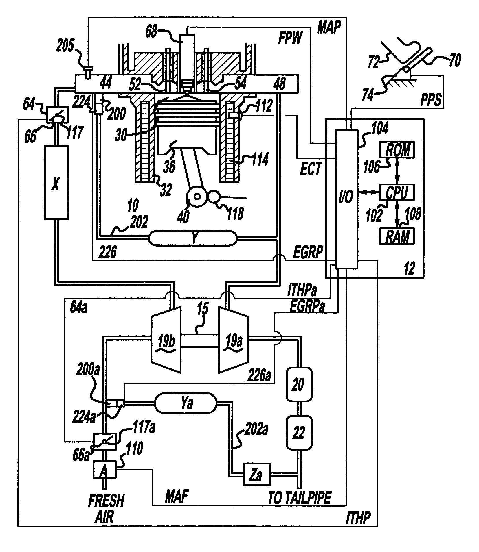
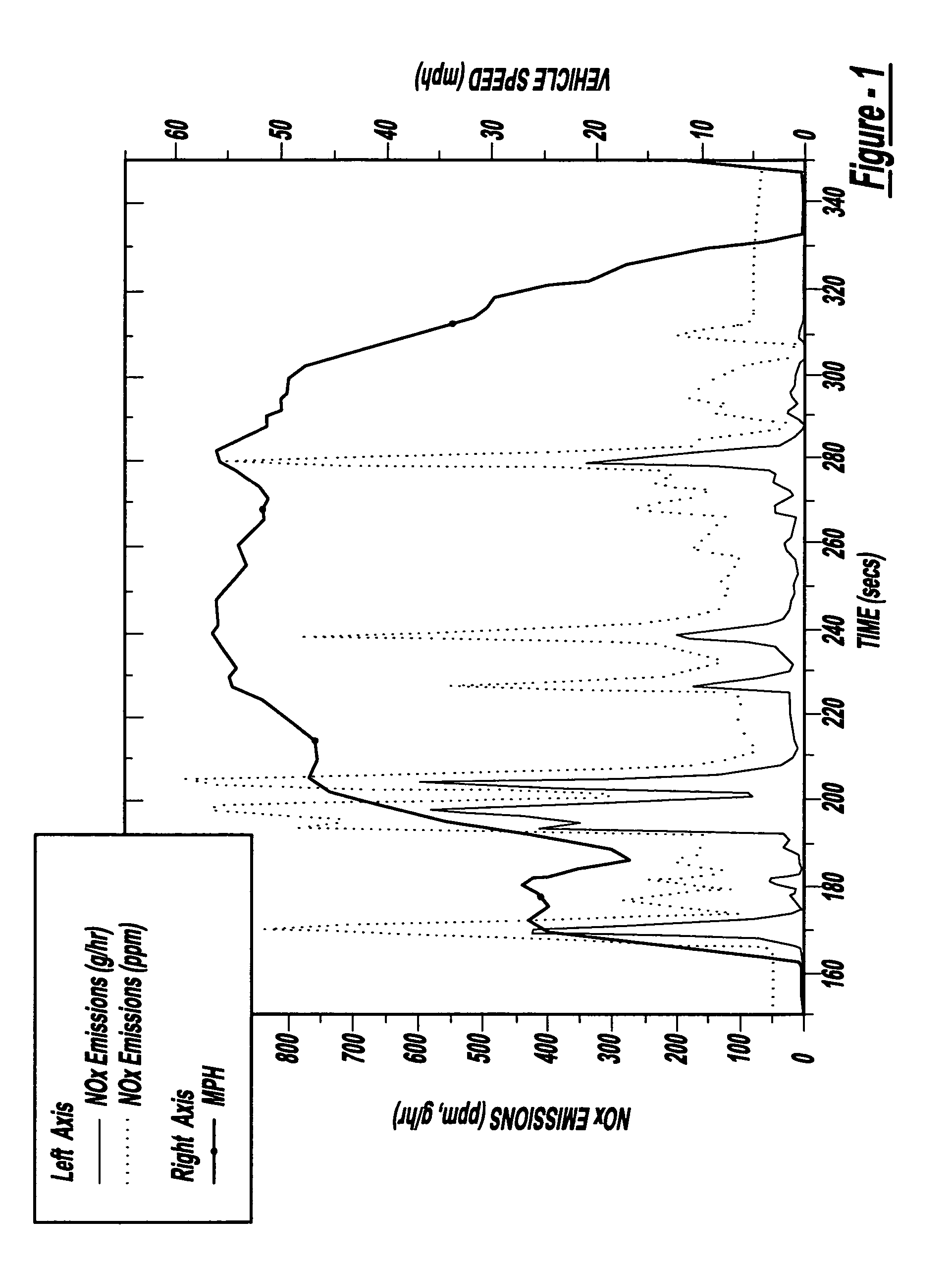
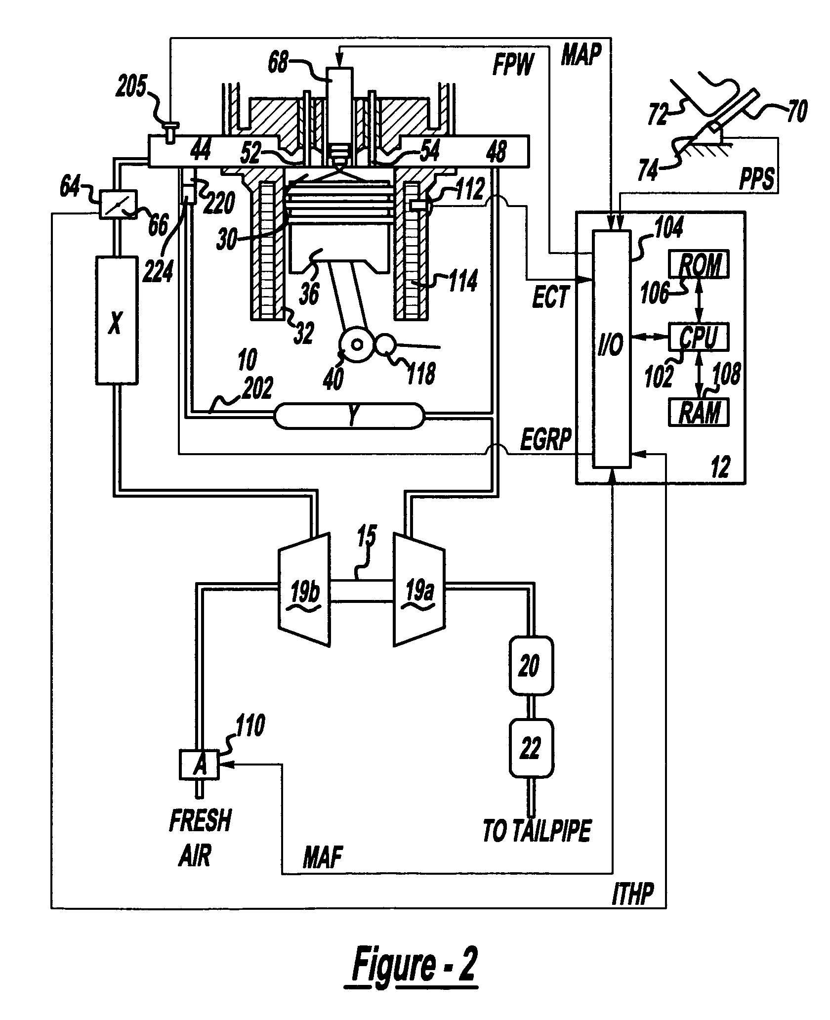
[0031]FIG. 1 shows NOx emissions during a transient emissions cycle of a vehicle powered by a typical turbocharged diesel engine. The Figure demonstrates that spikes in NOx emissions occur at various times during transient operation. Those spikes typically occur during hard acceleration and the primary reason for their existence is the interaction between the turbocharging system and the typical high pressure EGR system. During hard acceleration, the use of EGR is suspended in order to both divert exhaust flow through the turbine, which allows the turbocharging system to create boost, and increases air flow through the engine. However, without EGR, NOx emissions (concentration) increase dramatically. This comes at a time when the air and thus exhaust mass flow rate are very high causing NOx production to spike dramatically.

[0032]During the a typical urban driving cycle, the time in which the engine is operated under conditions that produce these spikes accounts for only about 4–5% o...


PUM


Abstract

The present invention is a dual-stage fuel injection strategy for compression ignition engines in which 15-40% of the fuel is injected into the combustion chamber no later than about −20 to −30 CA ATDC and as early as IVC. The remaining fuel is then injected in one or more fuel pulses, none of which start before about −20 to −30 CA ATDC. The fuel injected early in the compression stroke forms a lean mixture that burns with low soot and low NOx emissions. The combustion of that fuel serves to increase in-cylinder temperature such that the ignition delay of subsequent fuel injection pulses is short. This mode is utilized when it is predicted that a NOx spike is imminent. Various other alternative methods for reducing NOx spikes are also disclosed such as specialized EGR systems that can provide EGR with low manifold vacuum.

Description

CROSS-REFERENCE TO RELATED APPLICATIONS[0001]This application is a divisional application of U.S. patent application Ser. No. 10 / 248,634, filed Feb. 3, 2003 now U.S. Pat. No. 6,820,599, and is hereby incorporated by reference in its entirety for all purposes.[0002]This application is related to Ser. No. 10 / 248,633, titled, “SYSTEM AND METHOD FOR REDUCING NOx EMISSIONS DURING TRANSIENT CONDITIONS IN A DIESEL FUELED VEHICLE”, assigned to the assignee of the present application, and filed on the same day as the present application. The entire contents of Ser. No. 10 / 248,633 are hereby incorporated by reference into the present application.FIELD OF THE INVENTION[0003]The present invention relates generally to the control of an internal combustion engine powered by diesel fuel, and more specifically to reducing transient NOx generation produced by such a vehicle.BACKGROUND OF THE INVENTION[0004]Controlling NOx emissions in diesel engines has posed significant challenges to the automotive...

Claims


Application Information

Patent Timeline
Patent Type & Authority Patents(United States)
IPC IPC(8): F02M25/07F02B1/12F02B3/06F02B23/06F02B29/04F02D41/00F02D41/40
CPCF02B1/12F02B23/0696F02D41/005F02D41/403F02M25/0707F02M25/0709F02M25/071F02M25/0732Y02T10/47F02B29/0406F02B2275/14F02D41/0065F02D41/402F02M25/0731Y02T10/125Y02T10/44Y02T10/123F02B3/06F02M26/05F02M26/06F02M26/07F02M26/24F02M26/28Y02T10/12Y02T10/40
Inventor KURTZ, ERIC MATTHEWVANDERSLICE, JOHN H.
Owner FORD GLOBAL TECH LLC
Why Eureka
Try Eureka