Well production optimizing system

a production system and well technology, applied in the field of well production, can solve the problems of preventing the production of liquids, failure of the well to produce fluids utilizing the formation pressure only,

Inactive Publication Date: 2006-05-18
CASEY DANNY M
View PDF14 Cites 40 Cited by
  • Summary
  • Abstract
  • Description
  • Claims
  • Application Information

AI Technical Summary

Benefits of technology

[0004] In view of the foregoing and other considerations, the present invention relate...

Problems solved by technology

In the life of most wells the reservoir pressure decreases over time resulting in the failure of the well to produce fluids utilizing the formation pressure solely.
As the for...

Method used


Image

  • Well production optimizing system
  • Well production optimizing system
  • Well production optimizing system

Examples


Embodiment Construction

[0017] Refer now to the drawings wherein depicted elements are not necessarily shown to scale and wherein like or similar elements are designated by the same reference numeral through the several views.

[0018] As used herein, the terms “up” and “down”; “upper” and “lower”; and other like terms indicating relative positions to a given point or element are utilized to more clearly describe some elements of the embodiments of the invention. Commonly, these terms relate to a reference point as the surface from which drilling operations are initiated as being the top point and the total depth of the well being the lowest point.

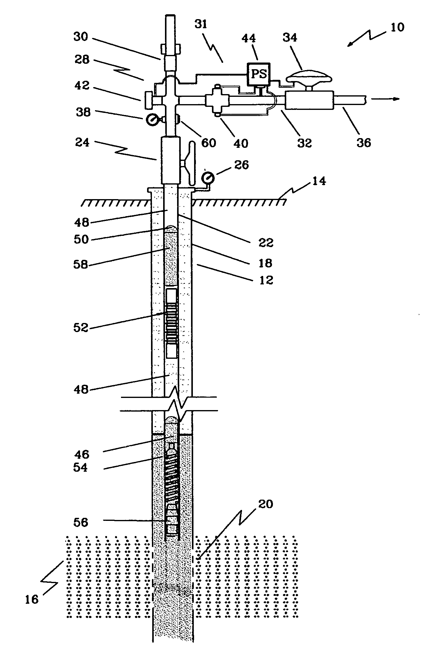
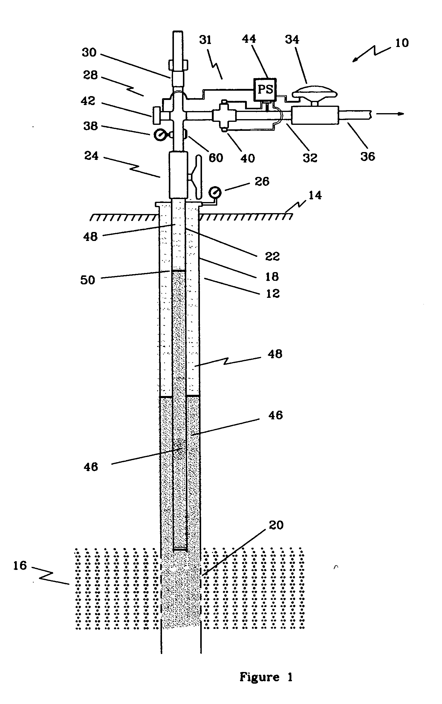
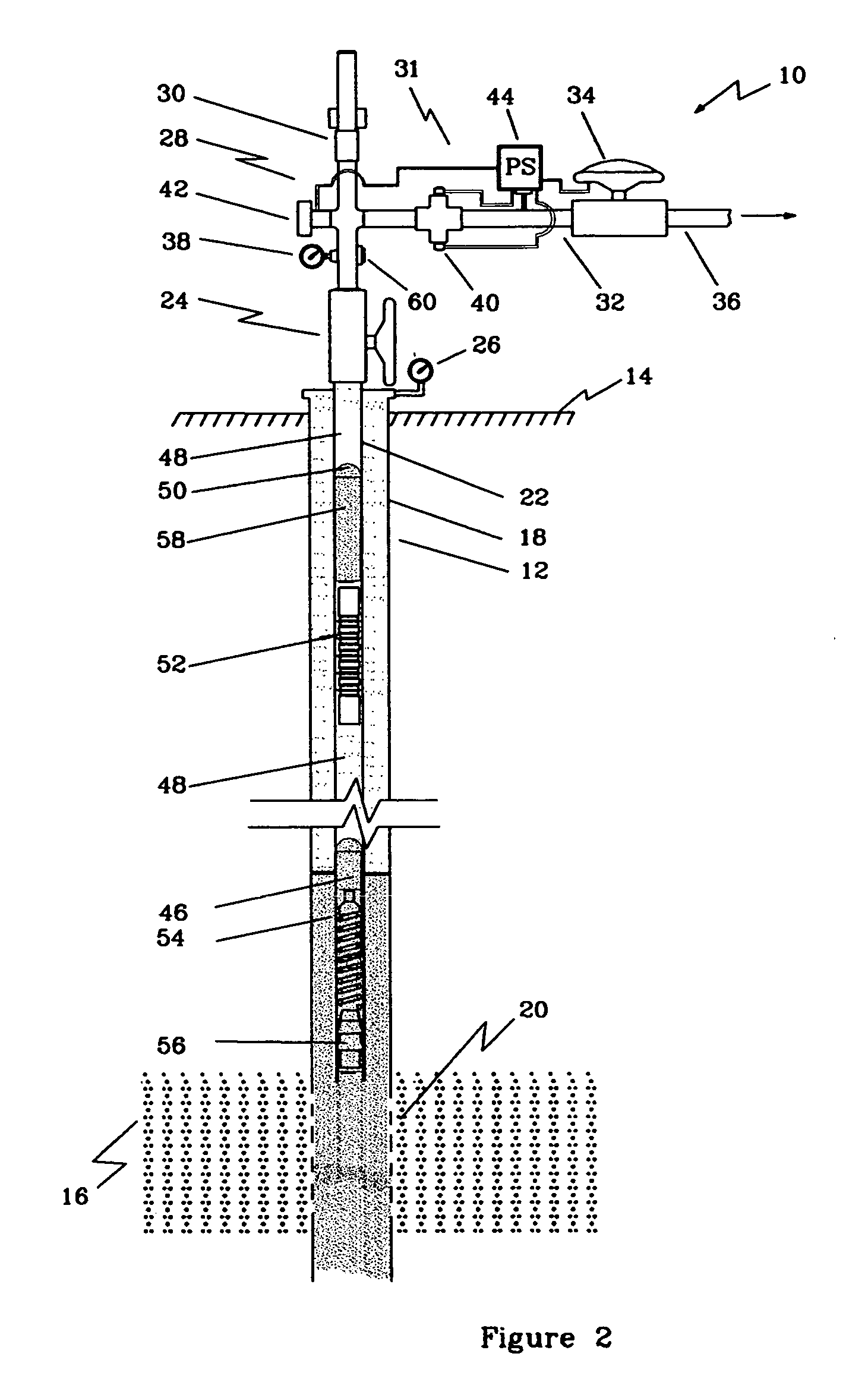
[0019]FIG. 1 is a schematic drawing of a well production optimizing system of the present invention, generally denoted by the numeral 10. The figure is illustrative of well under artificial lift production, which may include systems such as, but not limited to, gas lift, surfactant lift, beam pumping, and plunger lift. The well includes a wellbore 12 extending fro...


PUM


Abstract

A method and system for controlling a producing cycle in a well, during the production cycle, for optimizing production from the well including disrupting fluid in a wellbore with a pulse generator to create a pressure pulse transmitted through the fluid in the wellbore, detecting the pressure pulse created and the pressure pulse reflected from objects located within the wellbore, wherein the objects may include a liquid/gas interface and a producing apparatus such as a plunger, converting the detection of the pressure pulse and the reflected pressure pulses to a signal, computing the signals to determine the well status and controlling production of the fluid from the wellbore based on the well status.

Description

FIELD OF THE INVENTION [0001] The present invention relates to well production and more specifically to optimizing artificial lift production systems. BACKGROUND [0002] In the life of most wells the reservoir pressure decreases over time resulting in the failure of the well to produce fluids utilizing the formation pressure solely. As the formation pressure decreases, the well tends to fill up with liquids, such as oil and water, which inhibits the flow of gas into the wellbore and may prevent the production of liquids. It is common to remove this accumulation of liquid by artificial lift systems such as plunger lift, gas lift, pump lifting and surfactant lift wherein the liquid column is blown out of the well utilizing the reaction between surfactants and the liquid. [0003] Common to these artificial lift systems is the necessity to control the production rate of the well to achieve economical production and increase profitability. It is common for the production cycle of a particu...

Claims


Application Information

Patent Timeline
IPC IPC(8): E21B43/12
CPCE21B43/121E21B47/042E21B47/044E21B47/091E21B47/18E21B47/053E21B47/047E21B47/095
Inventor CASEY, DANNY MCSHANE
Owner CASEY DANNY M
Why Eureka
Try Eureka