Method and device for producing biogas
a biogas and biogas technology, applied in biochemistry equipment, biochemistry equipment and processes, water/sludge/sewage treatment, etc., can solve the problems of inefficient biogas production and high cost of biogas
- Summary
- Abstract
- Description
- Claims
- Application Information
AI Technical Summary
Benefits of technology
Problems solved by technology
Method used
Image
Examples
example 1
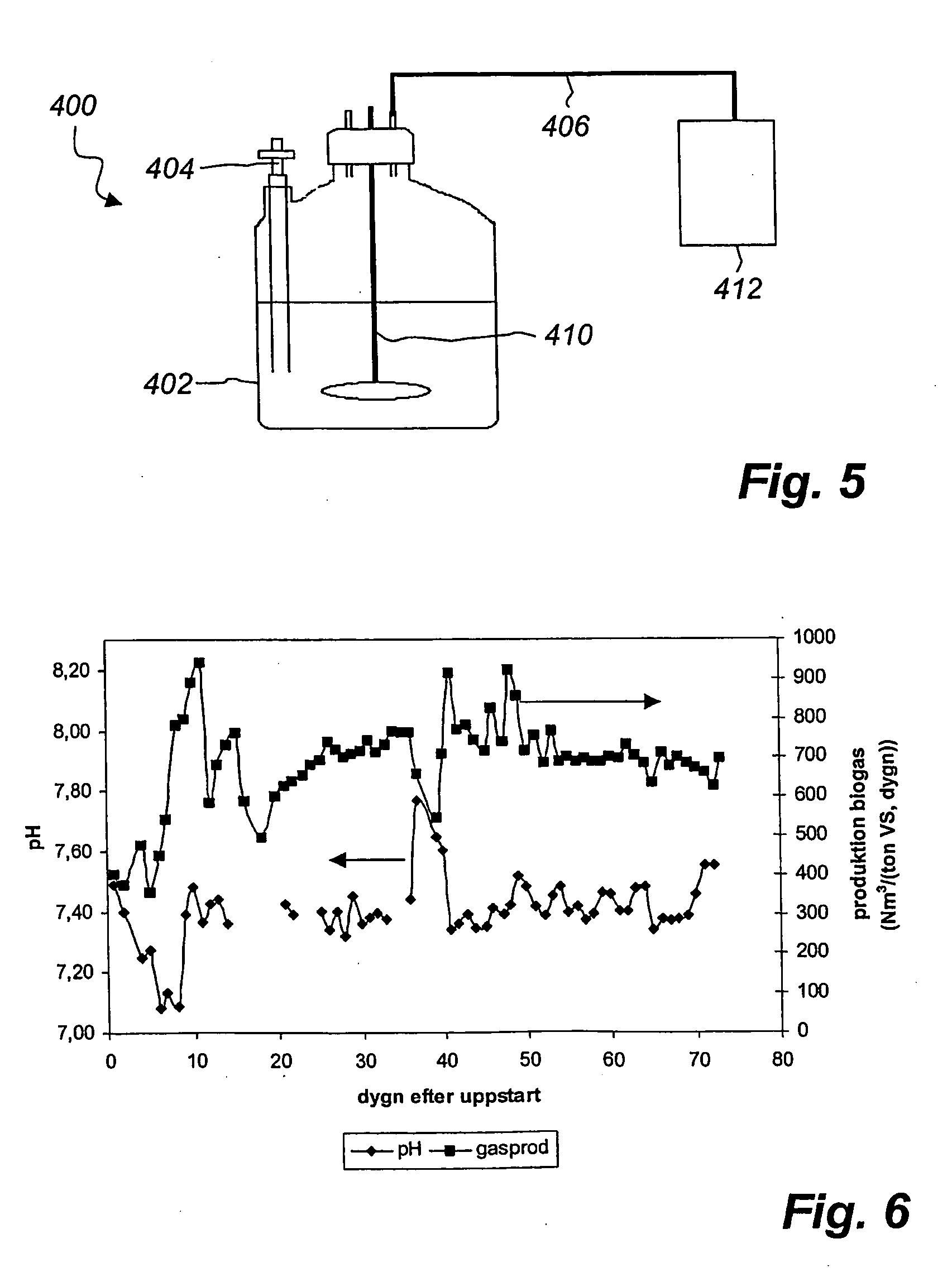
[0063] In a digestion experiment involving grain, an experimental device 400 which is shown in FIG. 5 was used, said device 400 having a gas-tight glass reactor 402 with a volume of 5 l. The liquid volume in the reactor 402 was kept constant at 3 l. A propeller agitator 410 (with a speed of 300 rpm) was used to achieve complete agitation in the reactor 402. A pipe 406 passed generated gas from the reactor 402 to a gas meter 412 measuring the volume of generated gas. A tight glass feed-through 404 was used for batch supply of grain and intermittent removal of formed digested sludge. A tempered space (not shown) was used to keep the temperature in the glass reactor 402 at 37° C.
[0064] When starting the experiment, 3 l of digested sludge from a full-scale digestion plant was introduced into the reactor 402. The sludge that was digested in the full-scale plant was of the origin that is evident from Table 1.
TABLE 1Origin of materials in full-scale plant.Unit by volumeSupplied product%...
example 2
[0069] A device 400 of the type described above was used for the experiment. At the start of the experiment, 3 l of digested sludge was charged from the above-mentioned full-scale plant. The origin of the digested sludge is thus evident from Table 1 above.
[0070] The substrate that was supplied to the reactor 402 consisted of grain and pasture plants. The grain consisted of 50% rye and 50% wheat and was present in the form of whole and screened grains. The grain was ground in the above-mentioned laboratory mill to a particle size of about 1 mm. The dry solids content of the ground grain was 91.6% by weight TS and the volatile solids content was 96.7% by weight VS. The pasture plants consisted of a mixture of clover and grass and had a dry solids content of 30.8% by weight TS and a volatile solids content of 92.2% by weight VS.
[0071] Four days a week, only ground grain was supplied to the reactor 402. The supply of grain amounted to 11.1 g, corresponding to 10 g of volatile solids. ...
example 3
[0075] A device 400 of the type as described above was used for the experiment. At the start of the experiment, 3 l of digested sludge from the above-mentioned full-scale plant was charged. The origin of the digested sludge is thus apparent from the Table 1 above.
[0076] Each day, 10 g of pelletised grain offal was charged to the reactor 402. The grain offal essentially consisted of husks, stems and rejected grains. The grain offal had first been dried in an oven and then pelletised in a pelletising machine. The pellets were ground in the above-mentioned laboratory mill to a particle size of about 1 mm. The dry solids content of the ground pellets was 88.6% by weight TS and the volatile solids content was 96.5% by weight VS. Thus, each day 8.55 g of volatile solids was charged, corresponding to barely 3 g of volatile solids per litre of reactor liquid and day. The ground pellets were mixed with 18 ml of water to a substrate mixture with a dry solids content of 35% by weight TS and a...
PUM
 Abstract
Description
Claims
Application Information
 - R&D
- Intellectual Property
- Life Sciences
- Materials
- Tech Scout
- Unparalleled Data Quality
- Higher Quality Content
- 60% Fewer Hallucinations
Browse by: Latest US Patents, China's latest patents, Technical Efficacy Thesaurus, Application Domain, Technology Topic, Popular Technical Reports.
© 2025 PatSnap. All rights reserved.Legal|Privacy policy|Modern Slavery Act Transparency Statement|Sitemap|About US| Contact US: help@patsnap.com


